Choosing the right installation position for a hot air blower built-in temperature sensor directly affects the accuracy of temperature reading, the timeliness of system response, and the long-term reliability of the entire thermal control loop. A poorly selected position can lead to delayed feedback, incorrect temperature judgment, and even unnecessary protection triggers during normal operation.
Upstream Pre-Heating Zone Placement for Real-Time Response
Some sensor units are installed in the narrow gap right before the heating core, where incoming cold air first makes contact with the pre-heated surface. This position captures the real-time temperature change the moment the heating element starts to generate heat, sending feedback to the control system far faster than positions further downstream. The sensor probe here is not directly exposed to the highest temperature zone, which reduces the risk of premature aging caused by long-term overheating. The installation structure uses a small embedded bracket that does not block the main airflow path, so it will not cause extra wind resistance or local turbulent flow that disrupts the normal heat exchange process.
Outlet Airflow Channel for Output Temperature Accuracy
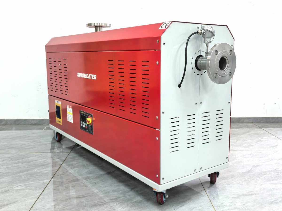
Many sensors are fixed at the straight section of the air outlet channel, 3 to 5 times the pipe diameter away from the heating core. This position sits in the fully mixed hot air zone, where the temperature distribution across the airflow cross-section stays highly uniform and stable. Readings taken here can accurately represent the actual temperature of the air that flows out to the working target, avoiding measurement errors caused by local overheating spots near the heating elements. The probe is inserted into the center of the airflow instead of touching the inner pipe wall, which eliminates the influence of pipe wall temperature deviation on the final measurement result. The installation opening on the pipe wall is fully sealed with high-temperature resistant filler to prevent any air leakage that may disrupt the original airflow state.
Shell Surface Buffer Zone for Overheat Protection
A small number of auxiliary temperature sensors are installed on the inner surface of the blower’s outer shell, in the buffer zone between the heating core and the outer plastic or metal casing. These positions monitor the accumulated heat that transfers to the outer structure during long hours of continuous operation, providing reliable data for the system’s overheat protection logic. The installation point is chosen away from the main heat conduction path, so it will not be affected by short-term temperature fluctuations of the internal airflow. The sensor is attached to the shell surface with a high thermal conductivity adhesive, ensuring the temperature of the shell can be transmitted to the sensing element quickly and accurately. This layout works as a second layer of safety monitoring, adding extra reliability to the entire hot air blower operation system.