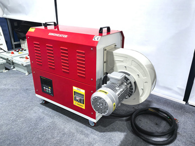
Precision Heating Techniques for Electronic Component Assembly Using Hot Air Blowers
Electronic manufacturing demands precise thermal control during component assembly to ensure solder joint reliability, adhesive curing, and material integrity. Hot air blowers provide localized, controlled heating essential for processes like surface-mount device (SMD) rework, connector bonding, and conformal coating curing. This guide outlines operational protocols, safety measures, and advanced techniques for integrating hot air systems into electronics production workflows.
Thermal Management Fundamentals in Electronics Assembly
Understanding Component Sensitivity
Electronic components exhibit varying thermal tolerances. Semiconductors, for example, typically withstand temperatures up to 260°C during soldering, while plastic housings may deform above 120°C. Polymers used in circuit boards (e.g., FR-4) degrade beyond 300°C. Operators must reference component datasheets to set temperature thresholds and avoid overheating.
Heat Transfer Mechanisms
Hot air blowers utilize convection heating, where heated air flows over components to transfer thermal energy. This method enables rapid temperature changes without direct contact, reducing mechanical stress. Adjustable airflow rates (typically 10–100 L/min) and temperature ranges (50–600°C) allow customization for different assembly tasks.
Step-by-Step Operational Protocol
Pre-Assembly Preparation
- Workspace Setup: Position the hot air blower on a stable surface at least 30 cm from flammable materials. Ensure ventilation systems can handle fume extraction, as heating adhesives or coatings may release volatile organic compounds (VOCs).
- Component Inspection: Use magnification tools to check for pre-existing damage. Clean surfaces with isopropyl alcohol (≥99% purity) to remove contaminants that could affect heat transfer.
- Fixture Alignment: Secure components in jigs or vacuum holders to prevent movement during heating. For SMD rework, align the nozzle to cover the entire solder pad area without touching adjacent components.
Temperature and Airflow Calibration
- Profile Programming: Input heating profiles into the blower’s controller. For lead-free soldering, set temperatures to 245–255°C with airflow rates of 30–50 L/min. Adhesive curing may require lower temperatures (80–120°C) and longer dwell times.
- Nozzle Selection: Choose nozzles based on component geometry. Narrow nozzles (2–5 mm diameter) concentrate heat for small SMDs, while wide nozzles (10–20 mm) suit connectors or heat sinks.
- Preheating: Apply gentle heat (100–150°C) to the circuit board before focused heating to minimize thermal shock.
Controlled Heating Execution
- Gradual Ramp-Up: Increase temperature in 10–20°C increments, pausing at each stage to monitor component response. Use infrared thermometers to verify surface temperatures match setpoints.
- Uniform Coverage: Move the nozzle in a circular motion (5–10 mm/s) to distribute heat evenly. For multi-pin components, dwell on each pin for 2–3 seconds before transitioning.
- Cooling Phase: After reaching target temperature, reduce airflow by 50% and allow components to cool naturally. Avoid forced cooling with compressed air, which may introduce moisture.
Advanced Techniques for Complex Assemblies
Multi-Layer Circuit Board Processing
When heating through-hole components on multi-layer PCBs, apply heat from both sides. Use a secondary hot air gun (set to 180–200°C) on the opposite side to ensure uniform solder flow without overheating the top layer.
Thermal Barrier Application
For temperature-sensitive adjacent components, apply thermal tape or silicone shields to block heat transfer. These barriers withstand temperatures up to 300°C and can be removed post-assembly without residue.
Real-Time Monitoring Systems
Integrate thermal cameras or pyrometers into the workflow to create heat maps of the assembly area. Algorithms can detect uneven heating and trigger adjustments to airflow or temperature settings automatically.
Safety and Maintenance Protocols
Personal Protective Equipment (PPE)
Operators must wear heat-resistant gloves (rated for ≥200°C), safety goggles with side shields, and flame-retardant clothing. Respirators with organic vapor cartridges are mandatory when handling adhesives or coatings.
Equipment Maintenance
- Nozzle Cleaning: After each use, soak nozzles in acetone for 10–15 minutes to remove solder residue. Use soft-bristled brushes to avoid scratching internal surfaces.
- Air Filter Replacement: Inspect pre-filters monthly and replace them when clogged. HEPA filters in the air supply system should be changed every 200 operating hours.
- Calibration Checks: Verify temperature accuracy quarterly using NIST-traceable thermocouples. Adjust controller settings if deviations exceed ±5°C.
Emergency Procedures
- Overheating Response: If components exceed maximum rated temperatures, immediately cut power and move the assembly to a fireproof surface. Do not attempt to remove melted parts until cooled.
- Airflow Blockage: Install pressure sensors in the air supply line to detect obstructions. The system should automatically shut down if airflow drops below 10 L/min.
By adhering to these protocols, manufacturers can achieve consistent, defect-free assembly results while extending equipment lifespan. Continuous training on thermal management principles and equipment operation ensures operators maintain proficiency in this critical manufacturing process.


