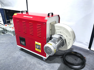
Precision Heating Techniques for Heat-Shrink Tubing Installation on Electrical Cables
Heat-shrink tubing provides critical insulation and mechanical protection for electrical cables. Proper installation using industrial hot air blowers ensures reliable performance while avoiding material degradation. This guide details operational protocols for achieving optimal shrinkage in wire harnessing, component sealing, and environmental protection applications.
Pre-Installation Preparation and Material Selection
Tubing Sizing and Material Compatibility
Select heat-shrink tubing with an inner diameter 10-20% larger than the cable’s outer diameter. For example, a 6mm cable requires 8-10mm diameter tubing to accommodate shrinkage ratios of 2:1 or 3:1. Polyolefin-based tubing suits general-purpose applications, while fluoropolymer variants withstand temperatures up to 200°C for automotive underhood wiring.
Verify compatibility with adhesive-lined tubing when sealing against moisture. The inner hot-melt adhesive layer activates at 85-105°C, creating waterproof seals when properly heated. For high-vibration environments, choose cross-linked tubing with 500% elongation resistance to prevent cracking.
Cable Surface Preparation
Remove oxidation layers using 240-grit sandpaper before installation. Clean cables with isopropyl alcohol to eliminate conductive residues that may cause arcing. For stranded wires, twist individual conductors tightly to maintain uniform shrinkage alignment.
When working with aluminum conductors, apply anti-oxidant paste to prevent galvanic corrosion at termination points. Ensure cable bends exceed minimum radii specified by the manufacturer to avoid tubing splitting during shrinkage.
Hot Air Blower Configuration and Temperature Control
Nozzle Selection and Airflow Dynamics
Use conical nozzles with 8-12mm exit diameters for precise heating of 10-15mm diameter tubing. For larger cables (25mm+), select wide-slot nozzles to maintain even heat distribution across the circumference. Position nozzles 15-25mm from the tubing surface to prevent localized overheating.
Adjust airflow to 2-3 m/s velocity when working with thin-wall tubing (0.2-0.5mm). Thicker wall variants (1.0-2.0mm) require 4-5 m/s velocities to achieve uniform internal heating. Monitor temperature with infrared thermometers to maintain 120-180°C ranges depending on material specifications.
Motion Control Systems for Uniform Shrinkage
Implement linear motion actuators to move hot air nozzles along the cable axis at 50-100mm/s rates. For complex harnesses with multiple branches, use robotic arms with 6-axis freedom to maintain consistent heating angles.
In automated production lines, integrate servo-controlled heating heads that synchronize with conveyor speeds. This ensures 3-5 second dwell times per shrinkage zone, critical for achieving 98%+ contact adhesion in high-volume manufacturing.
Shrinkage Process Optimization
Multi-Stage Heating Protocols
Apply initial 60-80°C preheating for 8-12 seconds to soften the tubing material. Progress to 120-140°C primary shrinkage temperature for 15-20 seconds, maintaining nozzle oscillation to prevent hot spots. Complete with 100-110°C post-shrinkage annealing for 5-8 seconds to relieve internal stresses.
For adhesive-lined tubing, extend primary heating to 25-30 seconds to fully melt the inner hot-melt layer. Verify adhesive flow by checking for 1-2mm extrusion at both tubing ends, indicating complete seal formation.
Environmental Compensation Techniques
In cold workshops (<15°C), preheat cables to 25-30°C using infrared lamps to reduce thermal shock. For humid environments (>70% RH), use desiccant chambers to dry tubing for 2-4 hours before installation.
When working at altitudes above 2,000 meters, increase heating times by 15-20% to compensate for reduced air density affecting heat transfer efficiency.
Quality Assurance and Defect Prevention
Visual Inspection Criteria
Post-shrinkage tubing should exhibit:
- Uniform wall thickness with <5% variation
- Complete coverage of solder joints and termination points
- Smooth surface without wrinkles or “cold spots”
- Adhesive flow confirmation in double-wall variants
Use borescopes to inspect internal shrinkage in confined spaces. For critical applications like medical device wiring, perform dielectric strength testing at 2kV AC for 1 minute to verify insulation integrity.
Common Defect Remediation
Address incomplete shrinkage by reapplying focused heat for 3-5 seconds while rotating the cable. For overheated sections showing charring, cut and replace the affected tubing segment.
When bubbles appear in adhesive-lined tubing, increase preheating time by 50% and reduce primary heating velocity by 30%. For split tubing caused by sharp cable edges, install protective silicone sleeves before shrinkage.
Safety and Maintenance Protocols
Thermal Management Systems
Equip hot air blowers with dual temperature sensors for redundant overheat protection. Set alarms at 220°C for polyolefin materials and 250°C for fluoropolymer variants.
Implement exhaust ventilation systems capturing 95%+ of fumes when working with adhesive-lined tubing. Provide operators with heat-resistant gloves rated for 200°C continuous exposure.
Equipment Calibration Procedures
Perform monthly verification of airflow rates using anemometers. Check nozzle alignment with laser positioning systems to maintain ±0.5mm accuracy.
Replace heating elements after 2,000 operating hours or when temperature variance exceeds ±5°C. Lubricate linear motion rails quarterly to prevent binding during automated shrinkage cycles.
By integrating precise temperature control, motion synchronization, and multi-stage heating protocols, industrial hot air blowers enable defect-free heat-shrink tubing installation. These techniques ensure electrical cables meet stringent insulation requirements across automotive, aerospace, and renewable energy applications.


