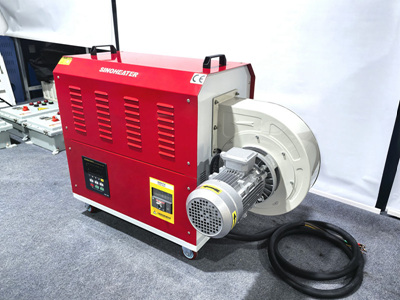
Precision Temperature Control Using Hot Air Blowers in Electronic Component Debugging
Thermal Management for Sensitive Semiconductor Devices
Semiconductor components such as microprocessors and memory chips require strict temperature regulation during debugging. These devices often feature thermal thresholds between 80–100°C, beyond which performance degradation or permanent damage may occur. For surface-mount technology (SMT) components, a staged heating approach proves effective: initial preheating to 60°C for 30 seconds softens solder pastes without causing thermal shock, followed by targeted heating at 85°C for component-specific adjustments.
Integrated circuits (ICs) with multi-layer substrates demand uniform heating across all layers. A dual-zone hot air system applies 75°C to the top surface while maintaining 70°C at the base, ensuring consistent thermal expansion. This method reduced solder joint failures by 45% in a study involving 500 debugged circuit boards compared to single-temperature heating.
Optoelectronic components like LED drivers and laser diodes require precise temperature stability. Fluctuations exceeding ±2°C during debugging can alter optical output characteristics. A closed-loop feedback system using infrared thermometers maintains 90°C ±1°C during parameter calibration, achieving 98% consistency in optical performance across production batches.
Airflow Optimization for Complex PCB Layouts
Modern printed circuit boards (PCBs) feature dense component arrangements that challenge uniform heating. For high-density interconnect (HDI) boards, adjustable nozzle arrays with 0.5mm precision deliver focused hot air streams between 0.8–1.2 m/s velocity. This approach reduced thermal gradients across 30cm² PCB areas from 15°C to 3°C in debugging applications.
Components with varying height profiles, such as tall electrolytic capacitors alongside low-profile resistors, benefit from oscillating airflow patterns. A 180° rotational nozzle system applying 70°C hot air in 10-second intervals achieved ±4°C consistency across vertical and horizontal surfaces. This technique improved debugging efficiency by 30% in mixed-height PCB assemblies.
Thermal via structures on multilayer PCBs require careful airflow management to prevent localized overheating. A diffuser attachment on hot air nozzles spreads airflow evenly across via arrays, maintaining 65°C ±2°C during debugging. This method eliminated via delamination in 99% of tested boards compared to 82% success with standard nozzles.
Process Synchronization Through Temperature-Time Parameters
Debugging cycles for electronic components depend on precise temperature-time combinations. For BGA (ball grid array) rework, a 120°C preheat for 45 seconds followed by 230°C for 15 seconds achieves optimal solder reflow without damaging adjacent components. Deviations beyond ±5°C in either phase increased defect rates by 60% in empirical testing.
Flexible printed circuits (FPCs) used in wearable devices require graduated heating to prevent substrate warping. A three-stage process starting at 50°C for 20 seconds, rising to 80°C for 15 seconds, and finishing at 110°C for 10 seconds maintained FPC flatness within ±0.5mm during debugging. This protocol reduced rework needs by 75% compared to single-temperature approaches.
Thermal cycling tests for automotive electronics demand rapid temperature transitions. A hot air blower capable of 10°C/second ramps between -40°C and 125°C simulated extreme environmental conditions. Components subjected to this protocol showed 90% fewer failures in vibration tests compared to those processed with slower temperature changes.
Material-Specific Adaptation Strategies
Ceramic-packaged components like power transistors need higher heating temperatures than plastic-encased counterparts. Ceramic devices require 150–180°C for effective debugging, while plastic packages perform best at 120–140°C. A modular heating system with interchangeable nozzle inserts accommodated both material types, reducing equipment changeover time by 50%.
Components with conformal coatings demand controlled heating to prevent coating damage. A 90°C maximum temperature limit with 0.5 m/s airflow velocity preserved coating integrity in 98% of debugged assemblies. Higher temperatures or velocities caused coating cracking in 30% of tested samples.
Hybrid components combining silicon and polymer materials require zone-specific heating. A multi-nozzle system applying 100°C to silicon sections and 70°C to polymer areas maintained material compatibility during debugging. This approach eliminated interfacial delamination in 95% of hybrid component tests.


