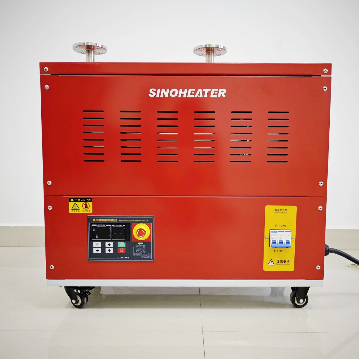
Hot Air Blower Heating Power Stepless Regulation Control Logic
Demand-Based Setpoint Tracking and Error Calculation Loop
The core of stepless regulation is a closed-loop control system that continuously adjusts power output to match a user-defined or process-driven thermal demand. This logic begins with the establishment of a target setpoint, which can be a specific outlet air temperature, a component surface temperature, or an environmental zone temperature, depending on the application. A high-speed temperature sensor, typically a thermocouple or RTD positioned at the critical measurement point (e.g., nozzle outlet, workpiece proximity), provides real-time feedback.
The control logic continuously calculates the error signal (E), which is the instantaneous difference between the setpoint (SP) and the process variable (PV): E = SP – PV. This raw error is the primary driver for all subsequent control actions. A positive error indicates the measured temperature is below the target, calling for increased heating power. A negative error indicates an overshoot, requiring a reduction in power. The system’s objective is to drive this error to zero and maintain it there, achieving a stable output temperature regardless of changes in airflow, ambient conditions, or thermal load.
To prevent rapid, jittery on-off cycling—a hallmark of simple bang-bang controllers—the stepless system employs a smoothing algorithm. This often involves calculating a moving average of the process variable over a short time window (e.g., 100-500 milliseconds) to filter out electrical noise or transient turbulence in the airflow that could cause false error signals. This filtered, stable PV is then used for the error calculation, ensuring the control response is based on genuine thermal trends, not measurement artifacts.
PID Algorithm: Proportional, Integral, and Derivative Action Synthesis
The sophisticated response to the error signal is governed by a Proportional-Integral-Derivative (PID) algorithm, the industry-standard logic for precise thermal control. This algorithm synthesizes three distinct corrective actions based on the same error signal, each addressing a different aspect of the system’s behavior.
-
Proportional Action (P): This is the immediate, present-moment response. The controller output is adjusted in direct proportion to the current error. The gain is defined by a tunable constant, Kp. A large error produces a large corrective action. However, pure proportional control alone leads to a “steady-state error” or offset, where the system stabilizes slightly below the setpoint because as the error shrinks, the proportional corrective force also shrinks, never quite reaching the target.
-
Integral Action (I): This component addresses the proportional control’s inherent offset. It sums (integrates) the error over time. Even a small persistent error will accumulate into a significant value, gradually increasing the controller’s output until the error is eliminated. The integral gain constant, Ki, determines how aggressively past errors are corrected. This action is crucial for achieving and maintaining exact setpoint accuracy but can cause “integral windup” if the error persists for too long (e.g., during startup), leading to overshoot.
-
Derivative Action (D): This is a predictive, damping component. It calculates the rate of change (derivative) of the error. If the temperature is rising very quickly toward the setpoint, the derivative action will anticipate a potential overshoot and begin to reduce the heating power before the setpoint is actually reached. The derivative gain constant, Kd, determines the strength of this damping effect. It improves stability and reduces oscillation, allowing for a faster response without overshoot.
The controller’s final output command is the sum: *Output = KpE + Ki∫E dt + Kd(dE/dt)**. The logic continuously solves this equation, typically thousands of times per second, to generate a smooth, dynamic power command.
Power Modulation Techniques: Phase-Angle and Zero-Cross Firing
The calculated output from the PID algorithm is a demand signal, typically a value between 0% and 100%. Translating this software command into a physically smooth variation of heat from a resistive heating element requires a power modulation technique. The two primary logic schemes for AC power control are Phase-Angle Control and Zero-Cross Firing (also called Burst-Fire or Time-Proportioning).
Phase-Angle Control operates on each half-cycle of the AC sine wave. The logic uses a thyristor (SCR or Triac) as a high-speed switch. For a given power level command (e.g., 50%), the controller allows the initial part of each sine wave to pass (the “conduction angle”) and blocks the remainder. At 50% power, it might trigger the thyristor to turn on at the 90-degree point of each half-cycle, allowing only the second half of each wave to pass to the heater. By precisely varying the firing angle from near 0 degrees (full power) to near 180 degrees (minimum power), it provides truly continuous, fine-grained control. However, this method chops the AC waveform, which can generate significant electromagnetic interference (EMI) and cause current spikes.
Zero-Cross Firing logic takes a different approach to minimize EMI. It only turns the thyristor on or off at the precise moment the AC voltage crosses zero. Control is achieved by rapidly cycling full power on and off over many AC cycles. For a 50% power command, the logic might deliver power for 10 full cycles and then cut power for the next 10 cycles. The proportion of “on” time to the total cycle time determines the average power. While this method is electrically quiet, it can cause low-frequency flicker in the heater’s glow and temperature ripple at the output if the cycle time is too long. Advanced logic uses a very short, fixed cycle period (e.g., 1-2 seconds) and varies the number of AC cycles within that period to achieve a smoother average power delivery.
Feedforward Compensation for Load and Airflow Disturbances
Pure feedback control (PID) reacts to an error after it has occurred. For a system with significant and measurable disturbances, a feedforward logic path is added to improve response. This is a predictive element that anticipates the effect of a disturbance and applies a corrective action preemptively.
The most critical disturbance in a hot air blower is the airflow rate. A change in fan speed directly changes the mass of air passing over the heater per second, which has an immediate and large impact on the outlet temperature. In a system with feedforward logic, the fan speed command (or a tachometer reading) is fed directly into the heater control algorithm. If the user increases the fan speed, the feedforward logic immediately calculates the additional cooling effect this will have and proactively increases the heater power command by a corresponding amount, before the temperature sensor detects a drop. This drastically reduces the magnitude and duration of the temperature deviation.
Similarly, a feedforward path can account for inlet air temperature. A cold ambient air intake requires more heating power to reach the same outlet temperature than warm air. A sensor measuring inlet temperature provides data for this preemptive adjustment. The feedforward logic uses a mathematical model of the system’s thermal dynamics to calculate the necessary power adjustment for a given change in airflow or inlet temperature, effectively “canceling out” the disturbance before it affects the controlled variable.
Adaptive Tuning and Operational State Management
The ideal PID constants (Kp, Ki, Kd) for a system at startup—when the heater is cold—are different from those needed at steady-state operation. Sophisticated control logic incorporates adaptive tuning or state-based gain scheduling to manage these different operational phases.
During the initial Cold Start Ramp-up, the system is far from setpoint, and the primary goal is to heat up as quickly as possible without exceeding safe component limits. The logic may use a high proportional gain (Kp) and temporarily disable or limit the integral term (I) to prevent windup. It may also enforce a maximum power limit or a maximum rate-of-temperature-rise limit to protect the heating element from thermal shock.
Once the temperature enters a Proximity Band (e.g., within 20°C of the setpoint), the logic switches to a different set of tuned constants optimized for stability and precision. The integral action is fully enabled to eliminate offset, and derivative action is engaged to dampen the approach and prevent overshoot.
At Steady-State Regulation, the logic may employ additional techniques like “dead band” or “hysteresis” around the setpoint. Within a very tight band (e.g., ±1°C), the controller may make only minimal adjustments or hold a constant power output to prevent “hunting”—small, constant corrections that cause wear on components and visible fluctuations in heater glow. The system maintains stability by responding only to deviations that exceed this narrow dead band.
Furthermore, the logic continuously monitors its own performance through metrics like the error integral or oscillation frequency. Some advanced systems feature auto-tuning routines that can inject a small, deliberate disturbance, observe the system’s response (overshoot, settling time), and automatically calculate and apply optimal PID constants for the current operating conditions, ensuring peak performance as the system ages or the operating environment changes.