
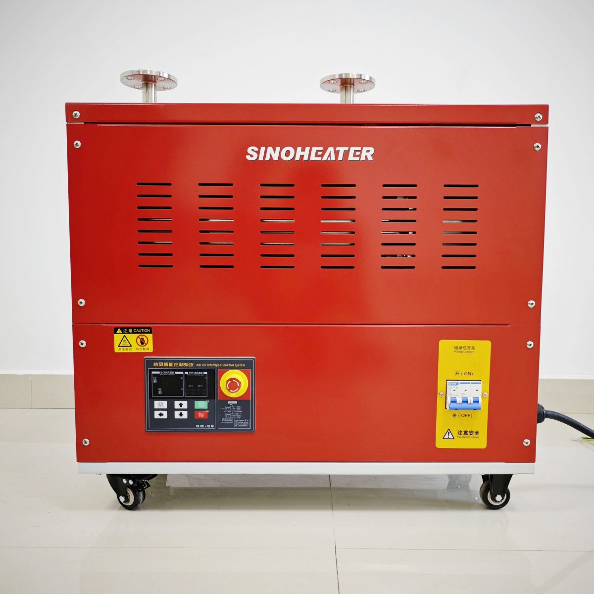
Hot Air Blower Dust Filtering Air Inlet Purification Working Flow
Pre-Filtration and Large Particulate Exclusion Stage
The purification workflow begins at the primary air intake grille, a structural component designed for initial gross filtration. This grille, typically made of molded plastic or stamped metal with a grid or mesh pattern, serves as the first line of defense. Its primary function is mechanical exclusion, preventing objects larger than approximately 5-10 millimeters—such as loose debris, tools, or fingers—from entering the blower housing and causing immediate fan damage or blockage. The apertures are sized to balance free airflow with safety and large particle rejection.
Immediately behind this grille, in the first chamber of the inlet duct, a coarse pre-filter is often stationed. This is usually a washable foam panel or a non-woven synthetic fiber mat with a relatively open structure. Its role is to capture larger dust particles, lint, hair, and fibers that passed through the grille. By trapping these materials early, it protects the more delicate and expensive primary filter downstream from rapid clogging and extends its service interval. This pre-filter operates primarily through direct interception and inertial impaction; as air navigates the tortuous path through the foam or fiber matrix, heavier particles cannot follow the streamlines and collide with and adhere to the filter material. This stage is critical for workshop environments where airborne debris like sawdust or textile fibers is prevalent, as it handles the high-volume, large-size contaminants efficiently.
Primary Filtration Media and Particle Capture Mechanisms
The core of the purification process occurs at the primary filter, a dedicated component designed for high-efficiency particulate air (HEPA) or high-performance filtration. The working flow here is defined by the filter’s media and its multi-mechanism capture strategy.
Air drawn by the fan passes through the filter media, which is a dense, pleated web of fine glass fibers or synthetic microfibers. The pleating dramatically increases the surface area available for filtration without proportionally increasing the physical footprint or airflow resistance. As contaminated air navigates this labyrinth, several physical mechanisms act in concert to remove particles:
- Interception: Particles following an airstream line that comes within one particle radius of a fiber are captured by direct contact. This is effective for particles in a mid-size range, typically around 0.3 to 1 micron.
- Impaction: Larger, heavier particles (generally above 1 micron) possess too much inertia to follow the curving air streamlines around filter fibers. They continue on their original trajectory and collide with, and stick to, the fibers. This is the dominant mechanism for pollen, large dust, and mold spores.
- Diffusion: Sub-micron particles, especially those below 0.1 micron, are so small that they exhibit Brownian motion—random jittering caused by collisions with gas molecules. This erratic path increases the probability that they will wander close enough to a fiber to be captured by interception or van der Waals forces. This mechanism is crucial for capturing ultrafine particles like smoke and viruses.
- Electrostatic Attraction (in Electret Filters): Many modern synthetic fiber filters are manufactured with a permanent electrostatic charge (electret). This charge creates an electric field that attracts and holds oppositely charged or neutral polarized particles, significantly enhancing capture efficiency for the most penetrating particle size (often around 0.3 microns) without increasing airflow resistance.
The combined effect of these mechanisms across the depth of the filter media ensures a high percentage of particles are removed from the airstream, protecting the sensitive internal components of the blower—the fan impeller, bearings, and heating element—from abrasive wear and fouling.
Sealing Integrity and Bypass Prevention
The most efficient filter is rendered useless if contaminated air can bypass it. Therefore, a critical parallel workflow to the filtration itself is ensuring perfect sealing integrity around the filter’s perimeter. The working principle is to create a sealed, gasketed channel that forces 100% of the intake air through the filter media.
The filter cartridge is housed in a dedicated compartment with precisely machined or molded sealing surfaces. A compressible gasket—made from closed-cell foam, silicone, or a soft rubber—runs around the entire edge of the filter frame. When the filter access door or panel is closed and secured (often with latches or screws), this gasket is compressed, forming an airtight seal. This design ensures that the only path of least resistance for incoming air is directly through the filter media. Any potential leak path, such as a warped frame, a missing gasket, or an improperly closed latch, would allow unfiltered, dusty air to be sucked directly into the blower, negating the entire purification system.
In high-reliability designs, this compartment is designed for “fail-sealed” operation. The geometry ensures that even if the filter becomes partially dislodged or the door is not fully latched, the air path becomes severely restricted or blocked before a significant bypass leak can occur, often triggering a drop in airflow that the user or a pressure sensor can detect.
Airflow Resistance Monitoring and Filter Condition Indication
As the filter loads with captured dust, its airflow resistance increases. This increasing static pressure drop across the filter is a key parameter in the working flow, as it directly impacts blower performance and signals the need for maintenance.
The system is designed with a known initial (“clean”) filter resistance. The fan and motor are sized to deliver the required airflow even when the filter reaches a predetermined maximum allowable resistance, known as the “final” or “clogged” resistance. The working flow includes monitoring this condition. In simple systems, this is a passive, user-driven observation: as the filter loads, the blower’s maximum airflow will audibly decrease, and its ability to maintain temperature at a given setting may diminish due to reduced mass flow.
In more advanced systems, an active monitoring workflow is implemented. A differential pressure switch or sensor is installed with one port on the dirty side (upstream) of the filter and one on the clean side (downstream). This sensor continuously measures the pressure drop. When the differential pressure reaches a set threshold—indicating the filter is loaded and approaching the end of its useful service life—the control system triggers a visual indicator, such as an LED changing from green to red, or a message on a digital display. This predictive maintenance feature ensures the filter is changed at the optimal time: not too early (wasting filter life) and not too late (which could strain the fan motor, reduce performance, or risk filter damage).
Post-Filtration Air Path Sanitization and Final Safeguard
After passing through the primary filter, the air is nominally clean. However, the purification workflow in some specialized blowers includes an additional, optional stage: post-filtration air treatment. This is common in applications requiring extremely clean, contaminant-free air, such as in electronics assembly or certain laboratory processes.
This stage may involve one of two mechanisms. The first is a second-stage, higher-efficiency final filter, sometimes an ultra-low penetration air (ULPA) filter, which provides a final “polishing” of the airstream to capture any particles that may have passed the primary filter or were shed from it. The second mechanism is thermal sanitization. In this workflow, the filtered air passes directly over the heating element, which operates at several hundred degrees Celsius. At these temperatures, any remaining biological contaminants (bacteria, mold spores) or volatile organic compounds are thermally destroyed or decomposed. The extreme heat effectively sterilizes the airstream.
A final safeguard in the workflow is the integrity of the internal air path downstream of the filter. This ductwork is designed to be smooth, seamless, and made of non-shedding materials like polished aluminum or stainless steel. The goal is to prevent the generation of new particulate contamination from within the blower itself after the air has been purified. Any internal components, such as fan blades or support structures, are also designed with this in mind, using materials and coatings that resist abrasion and corrosion, ensuring that the purified air delivered to the outlet nozzle remains as clean as when it exited the filter media.


