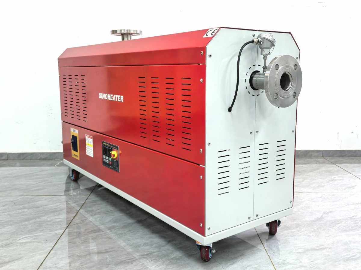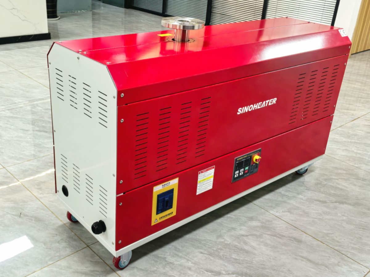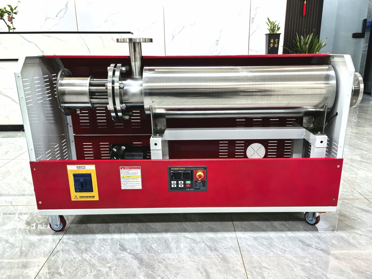
In demanding industrial environments where hot air blowers operate near their thermal limits, understanding and correctly setting high-temperature overload protection threshold parameters is not just a matter of equipment longevity—it’s a critical safety and process integrity requirement. These parameters define the precise conditions under which the system will intervene to prevent damage from excessive heat, balancing protection against unnecessary downtime.
Defining Core Temperature-Based Protection Thresholds
Motor Winding Temperature Sensor (Thermistor) Trip Points
The primary defense against overheating is monitoring the electric motor’s winding temperature. Embedded PTC or NTC thermistors provide direct thermal feedback. The key parameters here are the Trip Temperature and the Reset Temperature. The trip temperature is typically set 5-15°C below the motor insulation class limit (e.g., Class F insulation has a 155°C limit, so a trip might be set at 140-145°C). The reset temperature is set lower, often 15-30°C below the trip point, ensuring the motor cools sufficiently before a restart attempt is allowed, preventing cycling on a persistent fault.
Outlet Air Overtemperature Safety Limit
A separate, independent safety circuit monitors the temperature of the air exiting the blower. This acts as a final safeguard if the primary temperature control loop fails. The Safety Limit Setpoint is calibrated higher than the maximum operational setpoint but well below levels that could damage downstream equipment or pose a fire risk. For example, if a process requires 400°C, the safety limit might be set at 450°C. The response upon triggering this limit is typically a “hard” shutdown, requiring a manual reset after inspection.
Ambient Air Intake Temperature Compensation
In high ambient temperature settings, the cooling efficiency of the motor and electronics is reduced. Advanced systems include an intake air temperature sensor. The protection logic uses this reading to dynamically adjust the motor current overload threshold. As intake air temperature rises, the allowable continuous current draw is derated proportionally. This proactive compensation prevents the motor from exceeding its safe operating temperature due to inadequate cooling, even if the electrical current alone is within nominal limits.
Electrical and Current-Based Protection Adjustments
Derated Full Load Current (FLC) in High Ambient Conditions
The nameplate Full Load Current is specified for a standard ambient temperature (usually 40°C). In high-temperature environments, the thermal capacity of the motor is reduced. Therefore, the effective Derated FLC becomes the critical parameter for setting the thermal overload relay or electronic protector. This derating is based on the motor’s insulation class and the specific ambient temperature, often following IEC or NEMA derating curves. Setting the protector to the derated FLC, not the nameplate FLC, is essential.
Bi-Metallic Thermal Overload Relay Setting and Class
For devices using bi-metallic relays, the Current Setting Dial must be adjusted to match the derated FLC. Equally important is selecting the correct Trip Class (e.g., Class 10, Class 20, Class 30), which defines the time delay before tripping under an overload. In high-temperature environments, a faster trip class (like Class 10) may be warranted to provide quicker protection to heat-stressed windings, though this must be balanced against nuisance trips from legitimate startup currents.
Electronic Protector Configuration: I²t and Time-Current Curves
Electronic motor protection relays offer more precise parameterization. Key settings include the I²t (Current Squared Time) characteristic for overload modeling, which should be set to “On” for accurate thermal replica protection. The Time-Current Curve must be selected and, if adjustable, its parameters tuned. In high ambients, the curve may need to be shifted to account for the reduced thermal mass headroom, potentially leading to earlier intervention under sustained overload conditions.
Integration and System-Level Protection Logic
Heating Element Over-Temperature Protection
Beyond the motor, the heating assembly requires its own protection. Each heating zone or individual element may be monitored by a limit thermostat or a thermal fuse. The thermostat’s cut-out temperature is a fixed parameter, typically set close to the maximum withstand temperature of the sheath material (e.g., 750°C for certain stainless steels). Thermal fuses are one-time-use devices with a fixed rating. The key parameter is their rated trip temperature, which must be below the level that could cause element failure or ignition risk.
Control Board Thermal Protection and Logic Sequencing
The electronic control board is susceptible to heat. Protection is often provided by a board-mounted temperature sensor or a thermostat on the heat sink. The Board Overtemperature Threshold parameter will trigger a controlled system shutdown before components like power semiconductors are damaged. System logic should also incorporate a Startup Inhibit parameter if the internal temperature is above a safe level (e.g., 60°C), preventing a hot restart that could stress components.
Interlock and Feedback Monitoring Parameters
True system protection relies on interlocks. Parameters here include the Allowed Sensor Fault Time (how long a sensor failure is tolerated before shutdown) and the Heater Feedback Deviation Limit. If the current feedback from a heater circuit does not match the commanded state within a defined tolerance, it indicates a failed SSR or broken element, triggering a shutdown. The deviation limit is usually set as a percentage of the expected current.