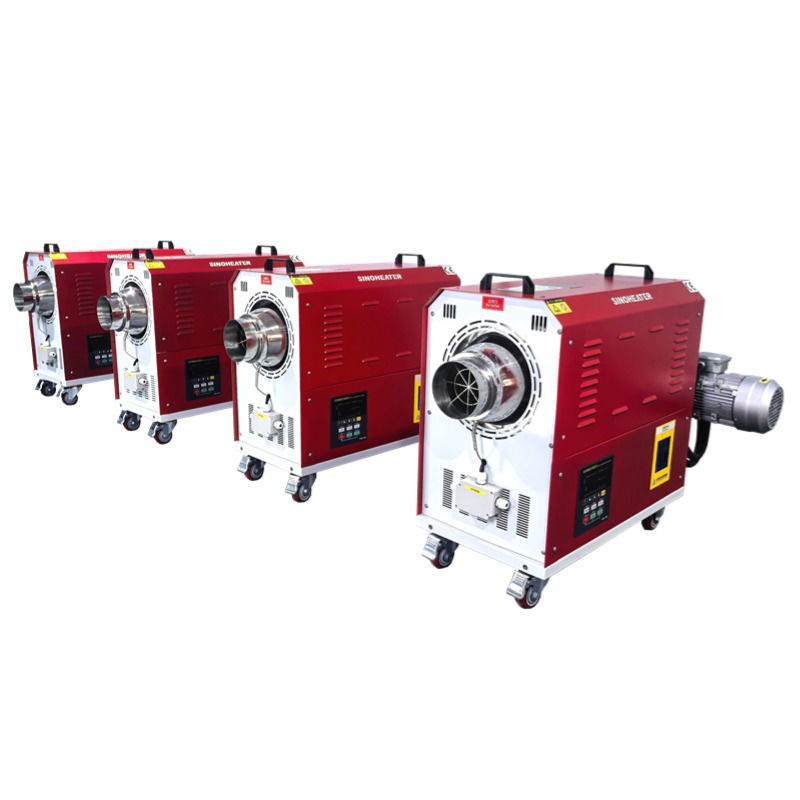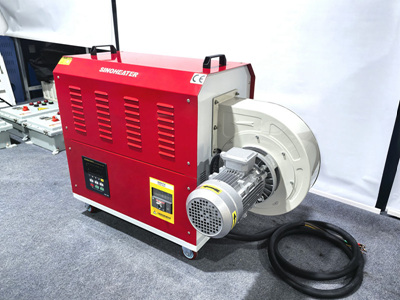
A well-planned internal layout of a hot air blower stainless steel heating tube directly determines its thermal response speed, long-term operational stability and consistent heat output performance. Every structural detail inside the tube is designed to match the airflow characteristics of common industrial hot air systems, avoiding unnecessary energy loss and potential safety risks that come with poorly arranged internal components.
Heating Element Alignment and Central Positioning
The internal heating elements are arranged along the central axis of the stainless steel tube, keeping an equal distance from the inner wall at every point. This symmetric layout ensures that heat radiates evenly to all surrounding areas, preventing local overheating spots that may cause premature aging of nearby insulation materials. The elements are fixed with high-temperature resistant supporting structures that do not block the airflow passing through the tube, so incoming cold air can make full contact with the heated surface the moment it enters the working zone. No loose moving parts are left inside this layout, which eliminates the risk of component shifting after repeated thermal expansion and contraction cycles over long use.
Insulation Layer Distribution and Gap Control
The insulation material filling the space between heating elements and the stainless steel outer wall is laid in a continuous, uniform density pattern, with no hollow gaps or uneven compression areas. This full-filling design blocks any possibility of electrical breakdown under high working temperature, while maintaining stable thermal conductivity that transfers excess heat outward properly. The thickness of the insulation layer follows a gradual adjustment rule along the length of the tube, matching the temperature gradient of the airflow that rises from the inlet to the outlet. This precise distribution prevents unnecessary heat accumulation inside the tube, and keeps the outer surface temperature of the stainless steel shell within a safe working range.
Airflow Guide Structure and Internal Channel Optimization
Small, smooth guide structures are set at intervals along the inner wall of the heating tube, which gently adjust the direction of passing airflow to create a mild turbulent state without causing excessive wind resistance. These structures help break up the laminar flow layer that often sticks to the tube wall, making sure more cold air can reach the surface of the heating elements to absorb heat efficiently. The layout also reserves a small buffer zone at both the air inlet and outlet ends, which avoids sudden temperature changes that may cause thermal shock to the core components. This arrangement works well with most standard hot air blower air supply systems, and supports consistent heat output even under long-hour continuous working conditions.