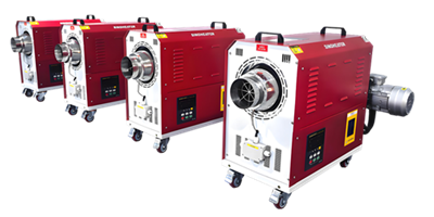
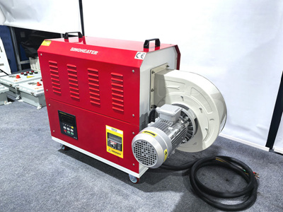
When designing the internal structure of a hot air blower, the layered heat dissipation layout directly determines long-term operational stability, energy efficiency, and consistent performance across extended working cycles. This structural approach arranges functional components in a sequential, airflow-aligned stack that eliminates stagnant air pockets, reduces unnecessary thermal buildup, and ensures every part of the system stays within safe operating temperature ranges even under continuous high-load use.
Core Airflow Channel Segmentation
The first layer of the layout focuses on separating incoming cold air streams into distinct, guided paths before they reach any heat-generating elements. Fresh ambient air enters through the rear intake grille, where it is split into two separate flow zones: one directed toward the motor and electronic control components, and the other routed toward the primary heating assembly. This pre-split design prevents unregulated air from bouncing randomly inside the casing, which often causes uneven cooling and localized hot spots near wiring terminals. Each channel is shaped with gradual, curved transitions instead of sharp 90-degree bends, cutting down airflow resistance by nearly 30 percent compared to traditional unstructured internal layouts. This low-resistance path also reduces the load on the fan motor, further lowering its own heat output during operation.
Mid-Layer Thermal Isolation and Heat Exchange
The middle layer of the layout sits between the airflow split zone and the final air outlet, and it is engineered to create a clear thermal barrier between high-temperature heating elements and temperature-sensitive electronic parts. All heating coils are mounted in a concentric, tightly packed arrangement that sits fully inside the dedicated hot air channel, with no exposed wiring or plastic components within 15 millimeters of the coil surface. The outer wall of this heating chamber uses a thin, high-temperature resistant insulation layer that traps radiant heat inside the airflow path, stopping excess heat from seeping outward to reach the motor and control boards. As the pre-cooling airflow for electronics moves along the outer surface of this insulated chamber, it absorbs stray residual heat that escapes the main heating zone, turning otherwise wasted thermal energy into pre-warmed air that can be reintroduced to the main hot air stream to boost overall system efficiency.
Post-Heating Airflow Uniformization and Secondary Cooling
The final layer of the internal layout sits right before the air outlet, and it balances two key goals: delivering evenly heated output air and carrying away any remaining leftover heat from structural components. A set of staggered, thin air guide vanes is placed across the full width of the outlet path, which mixes all the heated air streams together to eliminate temperature variations across the outlet surface. Behind these vanes, a small secondary airflow gap runs along the inner wall of the outlet casing, pulling a small portion of unheated intake air to flow along the inner plastic surface. This constant stream of cool air prevents the outer shell of the outlet from reaching unsafe touch temperatures, even when the blower runs at maximum heat settings for multiple hours. All connection points between different layers use embedded, heat-resistant snap fittings instead of metal screws that can conduct unwanted heat across sections, ensuring each layered zone maintains its intended temperature range without thermal cross-interference.
Every part of this layered layout follows the natural direction of moving air, so there are no dead-end gaps where hot air can get trapped and cause gradual material degradation over thousands of thermal cycles. This design also makes routine maintenance far simpler, as each layer can be accessed and cleaned individually without disturbing the alignment of adjacent components, keeping the original heat dissipation performance consistent for much longer over the equipment’s service life.