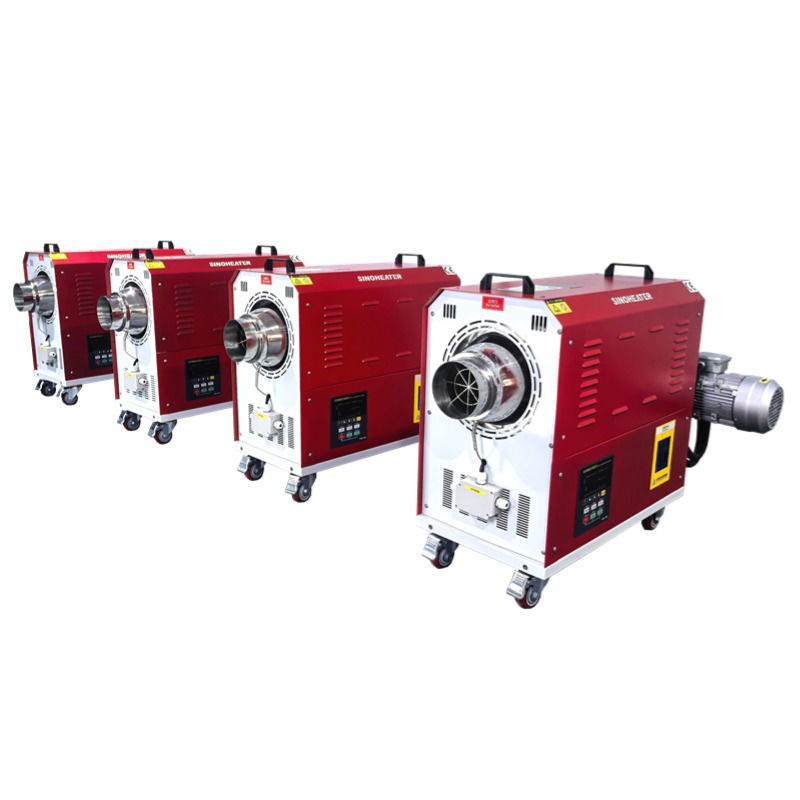
Hot Air Blower Temperature Closed-Loop Automatic Control Mechanism
Core Architecture of the Closed-Loop Control Framework
The entire closed-loop system is built on a continuous signal flow that connects temperature measurement, data processing, output adjustment, and real-time feedback, forming an unbroken cycle that never stops during normal operation. Unlike open-loop setups that run on pre-set fixed parameters without checking actual results, this mechanism constantly compares real working conditions against the target value, making tiny adjustments every few seconds to eliminate temperature drift. All components in the framework follow industrial electrical safety standards, with redundant protection points added to avoid single-point failure risks.
This architecture is designed to handle unexpected external disturbances, such as sudden changes in ambient temperature, unexpected opening of the system access door, or a batch of cold materials entering the working chamber. Even when these disturbances happen, the system can correct temperature deviations within a short window, rather than letting the error accumulate to an unacceptable level.
Real-Time Temperature Sampling Nodes
Multiple high-precision thermosensitive elements are placed at key positions across the hot air blower system, rather than only at a single outlet point. These sampling points cover the air inlet of the heating chamber, the direct surface of the electric heating assembly, the main hot air supply duct, the return air recirculation port, and the center of the target working space. Each sensor collects temperature data at a frequency of 5 to 10 times per second, ensuring no sudden temperature spike or local overheating goes undetected.
The data from different sampling points is not treated equally. The system assigns different weight coefficients to each set of readings, prioritizing the temperature value at the hot air outlet and the working chamber, while using the heating element surface reading as a critical safety reference. This weighted processing avoids misadjustment caused by a single abnormal data point from one sensor.
Signal Filtering and Data Calibration
Raw temperature data collected from the field often carries minor electrical noise caused by nearby high-power equipment or electromagnetic interference from the blower motor. Before the data is sent to the control logic unit, it goes through a multi-stage filtering process that removes transient abnormal readings without distorting the real temperature trend. Common filtering methods include moving average calculation, median value screening, and amplitude limiting processing, all of which are tuned to match the specific thermal inertia characteristics of hot air systems.
Regular automatic calibration routines are also built into the system. At pre-set idle intervals when no heating task is running, the control unit compares readings from all temperature sensors against a built-in reference value, and automatically corrects minor drift that accumulates after long hours of operation. This calibration step ensures measurement accuracy stays consistent even after months of continuous use.
Dynamic Adjustment Logic for Heating and Airflow
Once the filtered temperature data is sent to the control processing unit, the system runs a set of layered calculation rules to determine the exact output adjustments needed. These rules do not follow a simple on-off switch pattern, but instead use proportional, integral, and derivative calculations to make smooth, incremental changes that avoid sudden temperature overshoot. The logic is tuned specifically for the thermal inertia of hot air blowers, which means it accounts for the short delay between adjusting heating power and seeing a corresponding change in air temperature.
This adjustment logic also distinguishes between different operation stages. The rules used for the initial rapid warm-up phase are completely different from the rules used for the constant temperature holding phase, to balance heating speed and temperature stability.
Proportional-Integral-Derivative Tuning for Thermal Systems
The proportional part of the calculation responds directly to the current temperature error, outputting an adjustment signal that is proportional to the gap between the actual measured value and the user-set target temperature. The integral part accumulates small, persistent errors over time, slowly eliminating any static deviation that the proportional part alone cannot fully remove. The derivative part tracks the rate of temperature change, predicting upcoming temperature trends and making advance adjustments before the error grows too large.
For hot air blower systems, the PID parameters are not set to fixed values. The control unit automatically adjusts these parameters based on real-time operating conditions. During the warm-up stage when the temperature is far from the target, the proportional gain is increased to speed up heating. When the temperature approaches the set value, the gain is reduced to prevent overshoot that could push the temperature far above the target.
Blower Speed Coordination Control
Temperature control is not achieved only by adjusting electric heating power. The closed-loop mechanism also dynamically adjusts the blower motor speed to match different heating stages. During the initial warm-up phase, a slightly higher fan speed is used to spread heat across the entire system quickly, reducing local hot spots on the heating elements. When the system enters the constant temperature holding phase, the fan speed is fine-tuned to maintain consistent airflow, ensuring uniform temperature distribution across the entire working space.
This coordinated control also helps handle unexpected disturbances. If the system detects a sudden drop in return air temperature, it can slightly increase blower speed first to mix air more evenly, before adjusting heating power. This avoids the delay that would come from relying solely on heating power changes.
Fault Tolerance and Protection Interlock Mechanisms
A reliable closed-loop control system does not only focus on maintaining normal temperature. It also has layered fault tolerance logic that responds appropriately when any component encounters an anomaly, preventing secondary damage and ensuring operation stays safe even under partial failure conditions. All protection actions follow pre-defined priority rules, with safety interlocks always taking the highest precedence over any temperature adjustment command.
These mechanisms are designed to meet long-term continuous operation requirements. They can run for thousands of hours without manual intervention, and automatically record fault data for later troubleshooting when an abnormal event occurs.
Over-Temperature Hierarchical Response
When any temperature sampling point exceeds its pre-set safety threshold, the system triggers a layered response based on the severity of the deviation. For a minor, short-term overshoot that is only 2 to 3 degrees above the target value, the system first cuts heating power to zero and adjusts blower speed to maximum, waiting for the temperature to fall back to the normal range. If the temperature continues to rise and hits a higher critical threshold, the system activates a hardware interlock that completely disconnects power to the heating assembly, while keeping the blower running to dissipate residual heat.
The system also logs every over-temperature event with exact timestamp, temperature readings from all sensors, and the actions taken. This log data helps operators trace the root cause of the anomaly, rather than just resetting the system and letting the same fault happen again.
Sensor Anomaly Diagnosis and Backup Switching
The control unit constantly monitors the status of all temperature sensors. If a sensor sends a reading that is outside the normal physical possible range, or shows a completely unchanging value for a long period, the system marks that sensor as faulty. It then automatically switches to a pre-defined backup sensor at a nearby sampling point to continue providing temperature data for the closed-loop control, without triggering an immediate full system shutdown.
During this backup operation mode, the system sends a maintenance reminder to notify operators that the faulty sensor needs replacement at the next available idle window. This design prevents unnecessary unplanned downtime, especially for processes that require 24-hour continuous hot air supply.