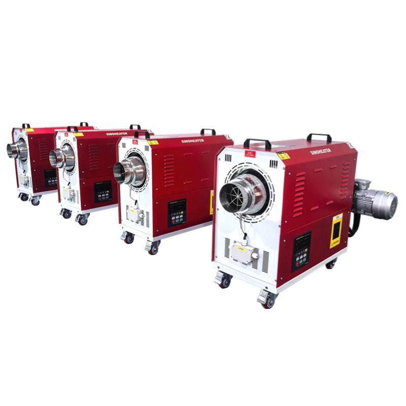
Hot Air Blower Constant Temperature Heating Stable Operation Logic
Foundation of Stability in Continuous Heating Systems
The operational logic for achieving constant temperature heating in a hot air blower is built on the principle of continuous dynamic equilibrium. This system maintains a precise balance between the thermal energy being added by the electric heating elements and the heat being lost through the blower’s air ducts, the working chamber walls, and the materials being processed. Unlike simple temperature control that only reacts after a deviation is measured, this logic actively predicts and compensates for predictable heat losses before they cause any measurable temperature drop, creating a proactive rather than reactive control loop.
This foundational logic treats the entire hot air system as a single thermal mass with multiple input and output pathways. Every component, from the heating coil to the air duct insulation, is included in the thermal inertia calculation that determines how quickly the system responds to control adjustments. This comprehensive approach prevents local hot or cold spots that would form if the control system only focused on the temperature reading from a single sensor.
Predictive Heat Loss Compensation Algorithms
The system continuously calculates the expected rate of heat loss based on real-time operating conditions. Key variables in this calculation include the difference between the internal air temperature and the external ambient temperature, the thermal conductivity of the chamber’s wall insulation, the airflow speed moving through the ducts, and the specific heat capacity of the materials currently inside the working space. The logic uses these inputs to generate a baseline heat output requirement that just matches the estimated losses, ensuring the system does not need to overheat and then cool down repeatedly.
When the system detects a change in any of these variables—such as a drop in ambient temperature around the blower—it preemptively adjusts the heating power output by a small, pre-calculated amount. This compensation occurs before the change in ambient temperature has any chance to affect the actual temperature inside the heated air stream, keeping the output temperature graph as a flat, stable line.
Thermal Inertia Mapping and Control Adaptation
Every hot air blower has a unique thermal inertia profile that defines how quickly its temperature rises when heating power is applied, and how quickly it cools when heating is reduced. The stable operation logic maps this profile during an initial commissioning or self-learning phase. It records the exact temperature response curve when different power levels are applied, creating a predictive model that links control actions to temperature outcomes with high accuracy.
This mapped model is then used to fine-tune all subsequent temperature adjustments. For example, if the model shows that a 10% increase in heating power typically raises the outlet air temperature by 5 degrees Celsius after a 12-second delay, the control system will apply that 10% power increase exactly 12 seconds before the temperature is predicted to start dropping, effectively canceling out the deviation before it appears on the sensor.
Multi-Zone Temperature Monitoring and Averaging
Stable temperature operation cannot rely on a single-point measurement, as local airflow turbulence or sensor placement can create misleading readings. The logic employs a multi-zone monitoring network that collects temperature data from at least three distinct locations: the immediate outlet of the heating assembly, the geometric center of the main air distribution duct, and the recirculation air return port. The system does not simply average these three readings. Instead, it applies a weighted average that prioritizes the most stable and representative sensor, while using the other two readings to validate consistency and detect anomalies.
If any single sensor reading deviates significantly from the other two for more than a few seconds, the system automatically flags that sensor as potentially faulty and temporarily reduces its weighting in the control calculation. This built-in redundancy prevents a single sensor failure from causing the entire system to lose temperature stability.
Dynamic Sensor Cross-Validation and Fault Tolerance
Every few minutes during normal operation, the control logic performs a silent cross-validation check between all active temperature sensors. It compares the rate of temperature change reported by each sensor when a known, small adjustment is made to the heating power. Sensors that show a response time or amplitude inconsistent with the known thermal characteristics of their location are marked for closer monitoring. This ongoing validation ensures that the system’s view of the internal temperature remains accurate over thousands of hours of continuous use, without requiring manual recalibration.
When a sensor is confirmed to be drifting or faulty, the system does not trigger an immediate shutdown. Instead, it smoothly transitions control reliance to the remaining healthy sensors, and sends a non-critical alert to the operator interface. This allows maintenance to be scheduled during the next planned downtime, rather than forcing an unplanned interruption to a sensitive heating process.
Real-Time Power Modulation for Elimination of Overshoot
The most common threat to temperature stability is overshoot—the tendency of a heating system to exceed the target temperature after a correction is applied, then swing back below the target, creating an ongoing oscillation. The stable operation logic prevents this through a real-time power modulation technique that breaks heating adjustments into a series of micro-steps, rather than applying one large correction. Each micro-step is calculated to bring the temperature exactly halfway between its current value and the target value, a method that asymptotically approaches the setpoint without ever crossing it.
This modulation is applied through high-frequency switching of the power supplied to the heating elements, using a duty cycle that can be adjusted in increments as small as 0.1%. The switching frequency is set high enough that the thermal mass of the heating elements cannot react to the individual on-off pulses, instead perceiving only a smooth, continuous level of heat output that corresponds to the average power over each short time window.
Anti-Oscillation Damping Through Predictive Modeling
Even with micro-step adjustments, some systems can still develop slow, low-amplitude temperature cycles due to delayed feedback or external disturbances. The logic includes an anti-oscillation damping module that monitors the temperature trend over a rolling 5-minute window. If it detects the beginning of a repeating cycle—where temperature rises and falls in a predictable pattern—it injects a tiny, counter-phase adjustment to cancel out the oscillation before it can grow in amplitude.
This damping action is not a simple delay or filter. It is an active interference based on a real-time Fourier analysis of the temperature signal, identifying the specific frequency of the oscillation and applying an opposing control signal at that exact frequency to neutralize it. This allows the system to maintain stability even when processing materials with irregular heat absorption patterns or when the blower door is opened briefly for inspection.
Integrated Response to Process Disturbances
Constant temperature operation must handle routine process disturbances without losing stability. Common disturbances include loading a batch of cold materials into the working chamber, briefly opening an access door for sample retrieval, or a sudden change in the humidity of the intake air. The logic categorizes each type of disturbance based on its expected impact magnitude and duration, and selects a pre-tuned response profile that minimizes temperature deviation while returning to the setpoint as quickly as possible.
For a known, short-duration disturbance like a door opening, the system might temporarily increase heating power by a fixed percentage for a pre-set time window, then automatically ramp back down according to a decay curve that matches the chamber’s thermal recovery characteristics. This pre-programmed response is faster and more precise than waiting for the temperature sensor to detect a drop and then reacting.
Material Thermal Load Adaptive Compensation
When new materials are introduced into the hot air stream, they absorb heat, acting as a temporary heat sink that can pull the air temperature down. The stable operation logic includes an adaptive compensation routine for this scenario. If the system is configured for a known material with a documented specific heat capacity, the operator can input the material’s mass and starting temperature. The logic then calculates the total thermal energy required to bring that mass to the target temperature, and schedules a proportional increase in heating output over the estimated warm-up period.
For processes where the material properties are unknown or variable, the system uses a different approach. It monitors the rate of temperature recovery after the initial drop caused by the material load. If the temperature returns to the setpoint more slowly than expected, it gradually increases the compensation power until the recovery rate matches the system’s standard performance profile, effectively learning the thermal load in real time.
Long-Term Stability Through Component Degradation Monitoring
Electrical heating elements and insulation materials slowly degrade over time, which can subtly change the system’s thermal response and undermine long-term temperature stability. The operation logic tracks key performance indicators over extended periods, such as the time required to reach the target temperature from a cold start, or the average power consumption needed to maintain a set temperature. A gradual drift in these indicators signals that a component may be wearing out.
When such a drift is detected, the logic does not simply increase power to compensate. Instead, it alerts the operator to perform preventive maintenance, while temporarily adjusting its internal control parameters to account for the changed performance. This allows the system to maintain temperature stability right up until the scheduled maintenance window, avoiding unplanned process interruptions due to sudden component failure.