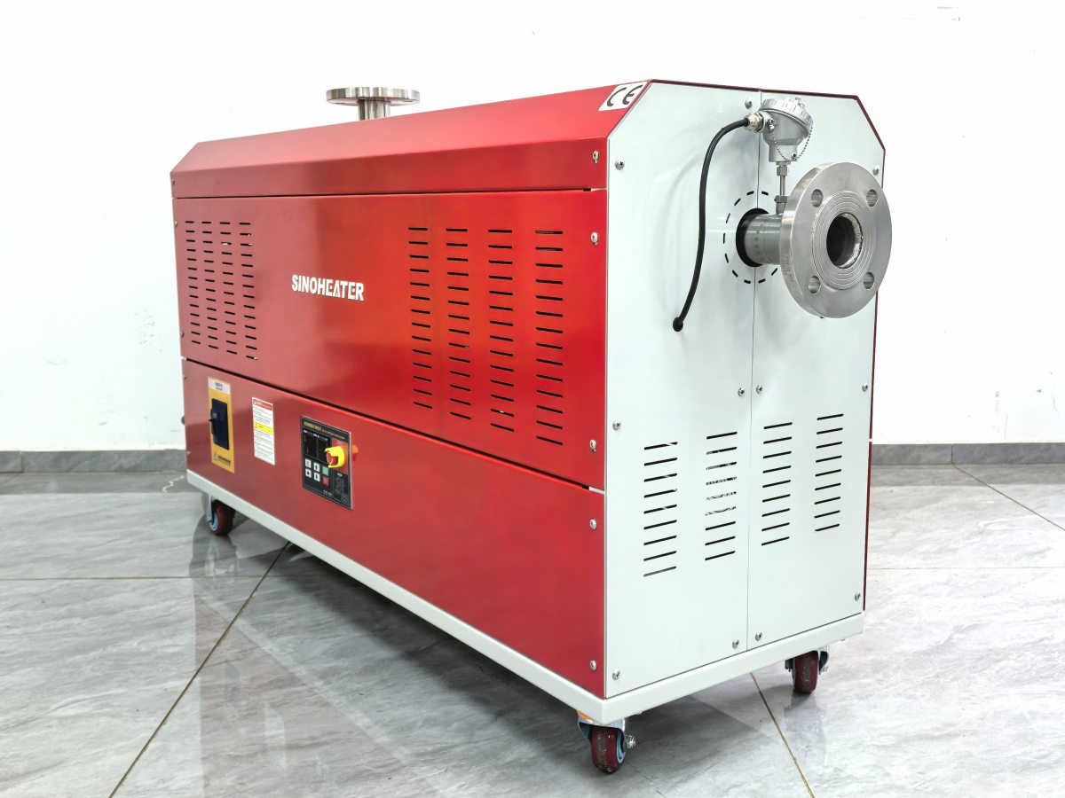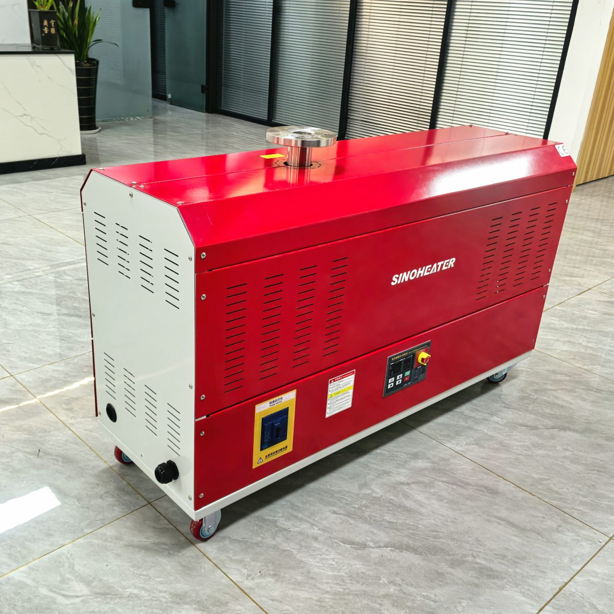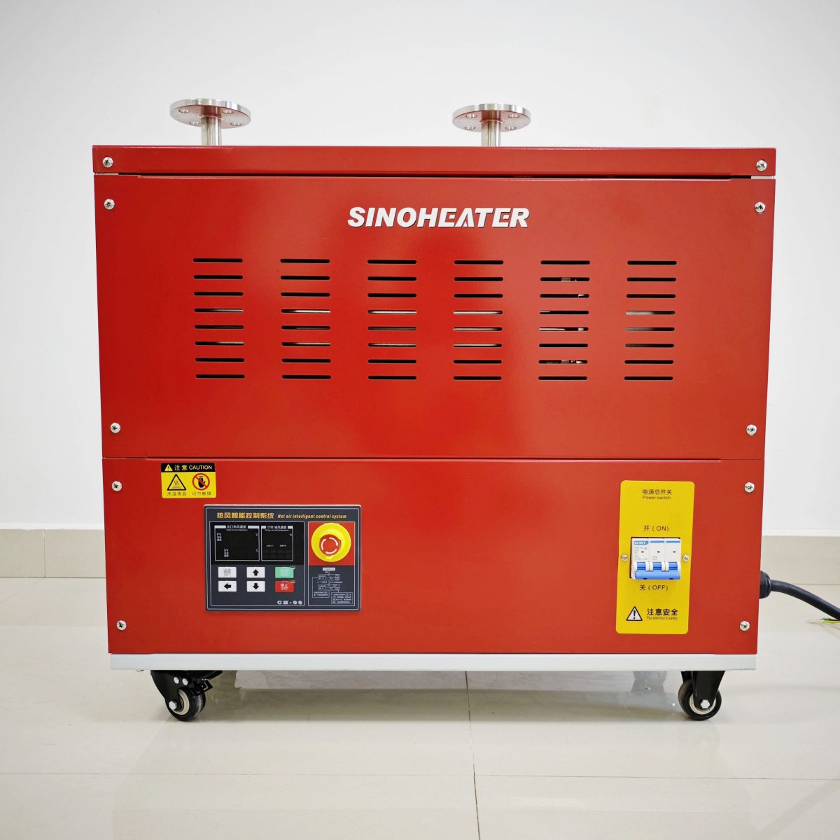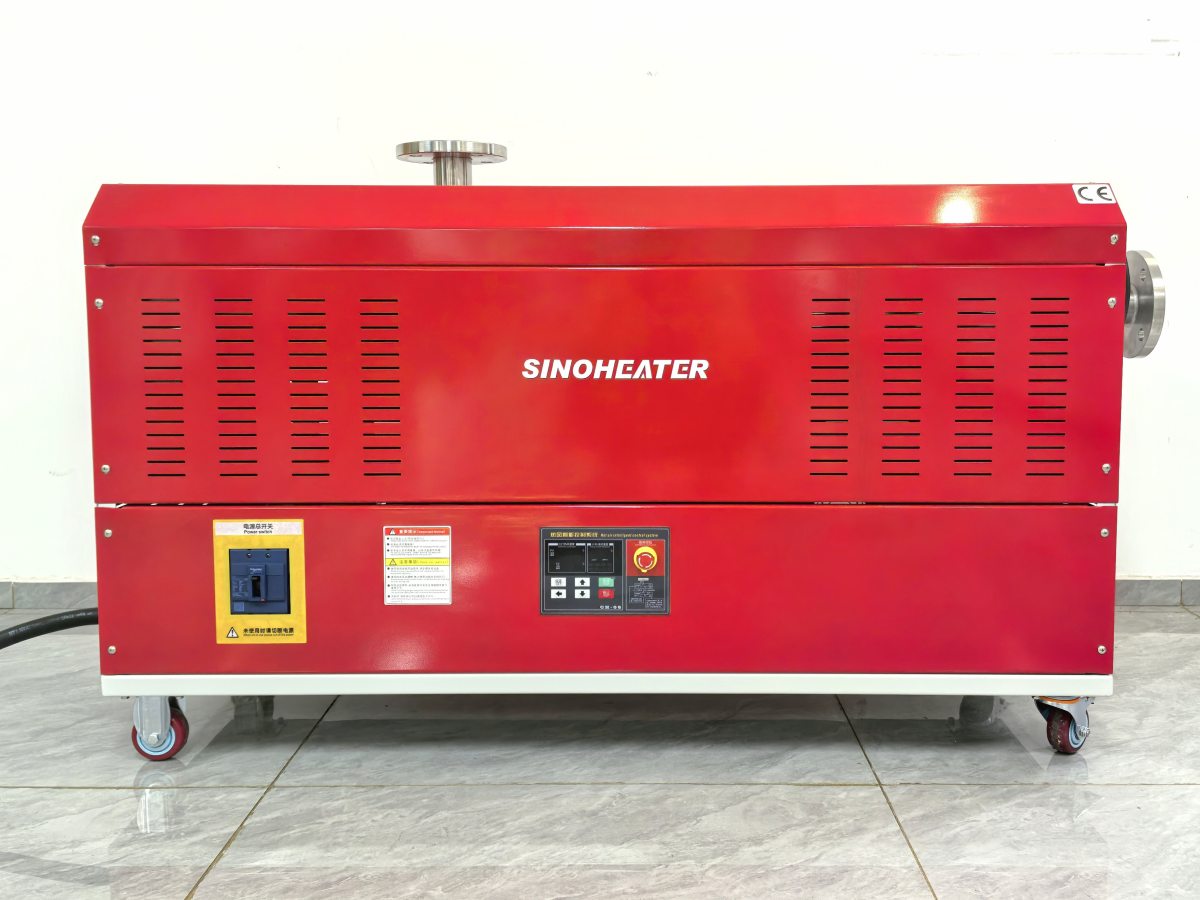
Core Mechanics of Air Backflow in Hot Air Blower Systems
Backflow in hot air blower setups occurs when pressurized heated air reverses its intended path and flows back toward the internal fan, heating element, or intake side of the system. This unwanted reverse flow usually happens when external system pressure spikes, or when the outlet side of the blower encounters sudden blockages that push air backward through the main duct. Without proper isolation measures, this backflow can carry superheated air, moisture, or process debris back into sensitive internal components, creating long-term wear and unexpected operational failures over time.
Many field technicians who service thermal processing equipment note that backflow events often go unnoticed during short daily operation cycles, but their cumulative effects add up quickly. Even small, intermittent reverse air flows can disrupt the fan’s rotational balance, cause uneven hot spots on heating elements, and pull unfiltered contaminants into the blower’s internal air path. The internal isolation design framework targets these hidden risks by placing protective barriers directly inside the blower’s core flow path, rather than relying on external add-ons that can be easily bypassed or damaged during regular use.
Pressure Threshold Calibration for Isolation Activation
A foundational part of this internal isolation design is setting precise, field-tested pressure thresholds that trigger the isolation mechanism the moment backflow pressure exceeds safe limits. Engineers map out the normal operating pressure range of the blower across all fan speeds and temperature settings first, then calibrate the isolation components to stay fully open during standard forward flow conditions, so they never disrupt normal air movement or reduce system efficiency. This careful calibration ensures the isolation system only engages when reverse flow pressure crosses the predefined safety line, avoiding unnecessary activations that would interrupt regular workflow.
This calibration process also accounts for minor, normal pressure fluctuations that happen during routine operation, such as temporary shifts in ambient air temperature or small changes in downstream airflow resistance. By filtering out these harmless minor variations, the internal isolation design avoids false triggers that would create unnecessary downtime, while still reacting instantly to the sharp, sustained pressure spikes that signal dangerous backflow is underway.
Structural Design Features of Internal Isolation Systems
The physical layout of the internal isolation system sits integrated directly between the blower’s fan chamber and the heating element section, creating a dedicated buffer zone that never interferes with the forward path of heated air during normal operation. All moving parts of the isolation mechanism are positioned outside the main high-temperature air stream during standard use, which reduces heat-related wear and extends the service life of the components far longer than external isolation solutions that sit in constant contact with hot air.
The internal housing of the isolation section uses smooth, rounded flow contours that match the shape of the blower’s main duct, eliminating sharp edges or narrow gaps that could trap debris, create unwanted turbulence, or reduce forward airflow efficiency. This seamless integration means the isolation system does not add unnecessary bulk to the overall blower structure, and it can be retrofitted into most existing standard hot air blower setups without major modifications to the surrounding ductwork.
Self-Clearing Mechanisms for Long-Term Reliability
A key practical feature of this internal isolation design is its built-in self-clearing function that prevents dust, process residue, or small debris from jamming the moving isolation components over time. Every time the blower runs in normal forward flow mode, the consistent positive air pressure pushes any loose particles away from the isolation mechanism’s moving parts, directing them back into the main forward air stream to be carried out toward the system outlet. This eliminates the common maintenance headache of having to disassemble the blower every few weeks to clear clogged isolation parts, a frequent issue with older external backflow prevention designs.
Field maintenance teams that work with these systems report that this self-clearing design drastically reduces unplanned service calls, even in dusty industrial environments where fine particulate matter is constantly circulating through the air stream. The mechanism also uses no fragile seals or easily degraded materials that would break down after repeated exposure to high temperatures, so it maintains full functional integrity even after thousands of hours of continuous operation.
Operational Safety and Performance Benefits of Integrated Isolation
Properly implemented internal backflow isolation eliminates a wide range of hidden safety risks that come with unprotected hot air blower systems. By stopping reverse air flow before it can reach the fan and intake side of the unit, the design prevents superheated air from being pushed back into unfiltered intake zones, where it could mix with fresh incoming air in ways that create unexpected overheating or even combustion risks in high-temperature processing environments. This level of protection is especially critical in facilities that process flammable materials, where even a small backflow event could pull heated fumes back into the blower’s internal components.
This design also stabilizes the overall performance of the hot air blower across all operating conditions. Without unexpected backflow disrupting the fan’s speed or creating uneven hot spots on the heating element, the system delivers far more consistent temperature and air flow output, which directly improves the quality of thermal processing work like coating curing, material drying, and surface treatment. Operators do not need to make constant manual adjustments to compensate for hidden backflow-related performance drops, which cuts down on human error and reduces unnecessary energy waste.
Post-Installation Validation Protocols for Isolation Performance
Industry standard operation manuals outline clear, step-by-step validation tests that teams must run after installing or servicing an internal backflow isolation system, to confirm it works as intended under real operating conditions. These tests include introducing controlled, measured reverse pressure spikes at the blower outlet, and verifying that the isolation mechanism engages fully within a fraction of a second to block all reverse air movement, while still allowing full unobstructed forward flow once normal operating conditions are restored.
Technicians also perform regular quarterly checkups that test the isolation system’s response time and seal integrity, using portable pressure sensors placed on both sides of the isolation barrier to confirm no unintended leakage occurs even at maximum rated backflow pressure. These documented validation steps ensure the system maintains full compliance with industrial thermal safety standards, and that it continues to deliver reliable backflow protection for the entire service life of the hot air blower unit.