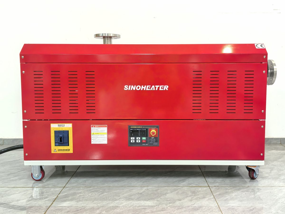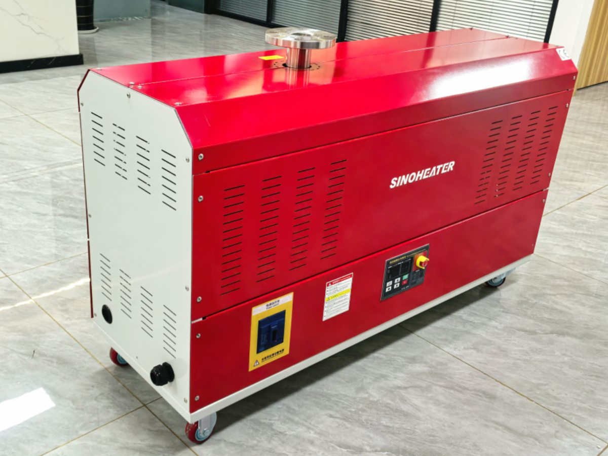
High-temperature hot air blower systems, especially those used in processes like industrial drying, chemical material handling, or thermal processing, face a significant risk of hot air backflow, which can damage upstream components, disrupt process stability, and create safety hazards. The anti-backflow control logic is a multi-layered, real-time operational strategy designed to proactively prevent this condition, rather than simply reacting to it after it occurs. This logic integrates sensor data, equipment states, and automated control actions to maintain unidirectional flow under varying load conditions.
Core Sensor Network and Condition Monitoring Logic
The system continuously monitors a network of pressure sensors installed at critical points: the blower outlet, key junctions in the delivery duct, and the inlet of the protected process or vessel. It compares these readings in real-time, not just for absolute values, but for the differential pressure (dP) across the system. The primary control rule is simple: the pressure at the blower outlet must always be maintained at a programmed minimum value higher than the pressure at the most downstream point. If this differential falls below a safe threshold—indicating a potential pressure equalization that could allow backflow—the logic triggers its first-stage response. Temperature sensors along the duct complement this, as a sudden temperature spike upstream could indicate hot gases moving in the wrong direction.
Multi-Stage Automated Response and Actuator Control
When a potential backflow condition is detected, the control logic executes a staged, prioritized response to correct it without causing a full system shutdown. The first and fastest action is typically to modulate the inlet guide vanes or variable frequency drive (VFD) of the blower to increase its output pressure and restore the positive pressure differential. Simultaneously, it sends a command to a fast-acting motorized damper installed in the main duct, instructing it to open further to reduce downstream resistance. If these adjustments do not restore the safe dP within a few seconds, the logic moves to the next stage: it can initiate a controlled ramp-up of the blower motor speed (within safe limits) or start a secondary “booster” fan if the system is so equipped. Throughout this process, the heating element’s power is often derated or temporarily cut to reduce the volume of hot air being generated until flow is stabilized.
Safety Interlocks and Failure Mode Management
The logic is built with redundant safety layers that account for component failures. A critical interlock is directly tied to the blower motor’s operational status. If the motor stops or fails, the logic immediately commands the main isolation damper (a normally closed damper) between the heater and the blower inlet to shut, physically blocking the duct. This prevents hot air from the process line from siphoning back through the idle blower. Furthermore, the control system constantly performs diagnostic checks on its own sensors and actuators. If a key pressure sensor fails, the logic can switch to a backup sensor or a calculated value based on other parameters, while logging a maintenance alert. In a total control system power loss, spring-return actuators are configured to fail in the “safe” position (e.g., isolation dampers close), ensuring a passive layer of protection against backflow.