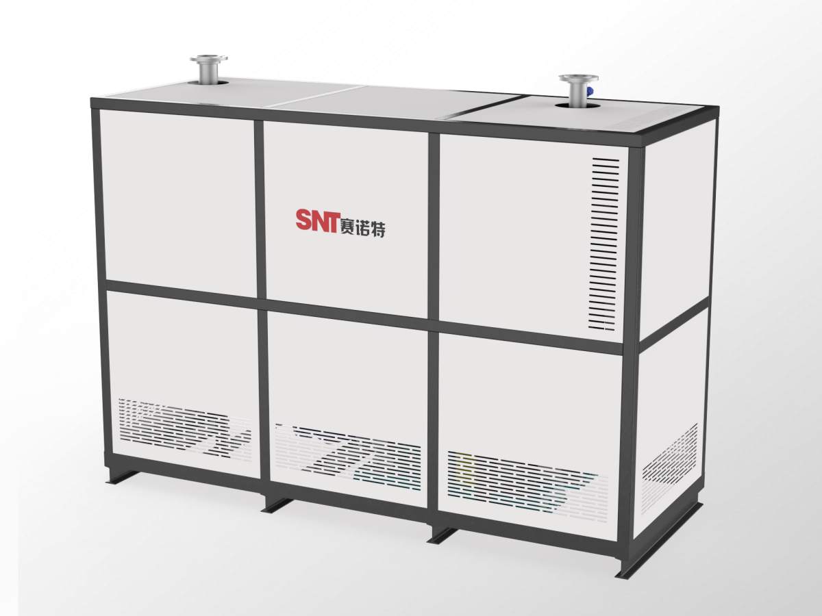
Variable frequency control has become a core technical approach for regulating hot air blower operation in modern industrial and commercial environments. It directly adjusts the rotational speed of the drive motor, which in turn modifies airflow, static pressure, and overall thermal output to match real-time operational demands. This type of control does not rely on mechanical dampers or bypass valves to restrict airflow, so it reduces unnecessary energy waste and minimizes mechanical wear across the entire system. Understanding the key performance indicators behind this control method helps operators set stable operating parameters, extend equipment service life, and maintain consistent thermal performance under varying load conditions.
Speed regulation accuracy under dynamic load changes
This indicator measures how closely the actual fan rotational speed aligns with the set target value when external conditions shift. When the system encounters sudden changes in ambient temperature, duct resistance, or heating element power draw, the control unit must adjust the output frequency smoothly without overshooting, stalling, or introducing noticeable speed fluctuations. Even under continuous long-cycle operation, the deviation between the commanded speed and the measured real speed should remain within a narrow, stable range, so that airflow delivery does not drift unexpectedly and disrupt downstream process requirements.
Energy efficiency ratio across full frequency spectrum
This indicator reflects the relationship between input electrical power and actual fan mechanical output at every possible operating frequency point. Since the shaft power of the fan follows the cubic law relative to rotational speed, even a small reduction in speed can produce a disproportionately large drop in power consumption. A well-calibrated variable frequency control system maintains high energy conversion efficiency not only at the rated operating point but also at low, medium, and intermediate speed settings, avoiding unnecessary heat loss inside the drive unit and preventing excessive reactive power from being drawn back into the supply line.
Response time and protection trigger consistency
This indicator tracks how quickly the control system reacts to new setpoint commands and how reliably it activates safety mechanisms when abnormal conditions appear. When an operator sends a new airflow demand signal, the system should ramp the motor speed up or down within a defined, predictable time window, rather than jerking to the new state or lagging for several seconds. It must also continuously monitor motor current, winding temperature, and output frequency stability, triggering soft shutdown or speed limiting actions immediately if overcurrent, overheating, or unexpected mechanical resistance occurs, to prevent permanent damage to the motor, heating assembly, and related air delivery components.