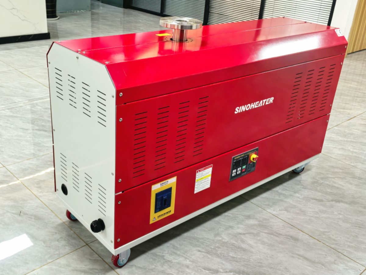
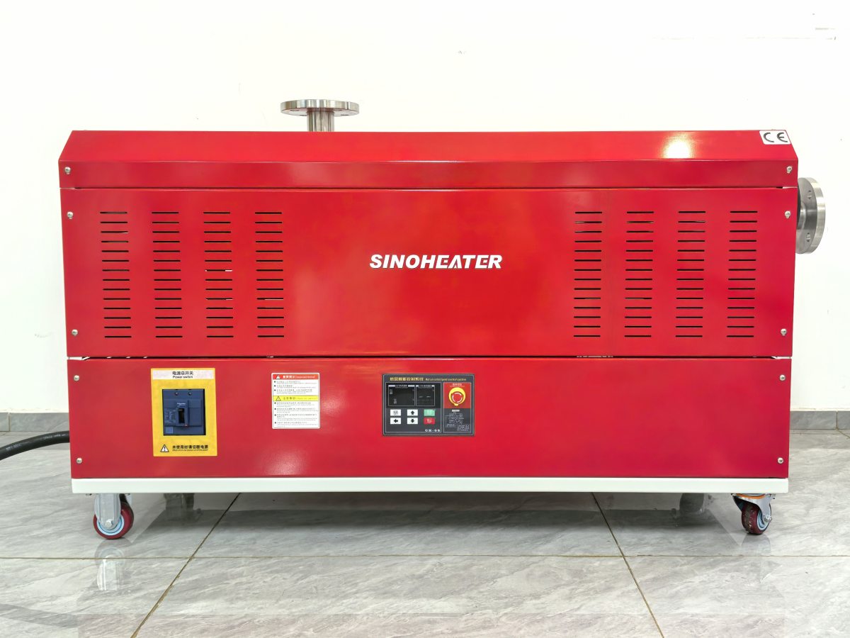
Adjustable air pressure output control in hot air blowers is achieved through integrated mechanical and electronic systems that manage airflow volume, velocity, and discharge characteristics. This control principle relies on precise coordination between fan speed regulation, internal duct geometry, and outlet restriction management to deliver consistent, repeatable pressure adjustments across a defined operational range. Real-world application data from industrial drying, curing, and heating processes confirms the reliability of these control methods under continuous thermal cycling and variable material resistance conditions.
Fan motor speed regulation and airflow volume management
The primary control mechanism adjusts the rotational speed of the blower’s centrifugal or axial fan motor, directly changing the volume of air moved per unit time. Variable frequency drives or electronically commutated motor controllers modulate electrical input to achieve smooth speed transitions, avoiding the stepped pressure changes associated with basic multi-speed switches. This speed-based control maintains a linear relationship between motor RPM and output air volume, allowing operators to set precise airflow rates that correspond to specific pressure requirements for different material processing stages. The control system continuously monitors motor load to prevent stalling or overload when external duct restrictions increase, automatically compensating to hold the set pressure point.
Internal duct geometry and variable venturi effect utilization
Within the blower housing, adjustable internal baffles or movable guide vanes alter the cross-sectional area of the airflow path, creating controlled venturi effects that convert velocity into pressure. By narrowing specific sections of the internal duct, the system increases airflow velocity, which raises dynamic pressure while reducing static pressure downstream. Conversely, widening the duct area decreases velocity and increases static pressure for applications requiring broader, softer airflow. This geometric control works in tandem with fan speed adjustments, enabling fine-tuning of pressure profiles without over-relying on motor power consumption. The positioning mechanisms for these internal components are designed for minimal airflow disruption, maintaining laminar flow characteristics even during adjustment cycles.
Outlet restriction and nozzle configuration adjustments
At the discharge point, interchangeable nozzles and adjustable outlet rings modify the final opening area through which heated air exits the blower. Smaller diameter nozzles create higher backpressure within the system, forcing the blower to work against greater resistance to maintain airflow, thereby increasing output pressure. Adjustable outlet rings provide continuous diameter variation without nozzle changes, allowing operators to dial in exact pressure settings for specific workpiece shapes or process requirements. The control system accounts for these outlet modifications by sensing pressure differentials across the final discharge section, automatically adjusting upstream fan speed or internal baffle positions to compensate and maintain the target pressure output. This closed-loop response ensures consistent performance regardless of nozzle configuration changes during operation.