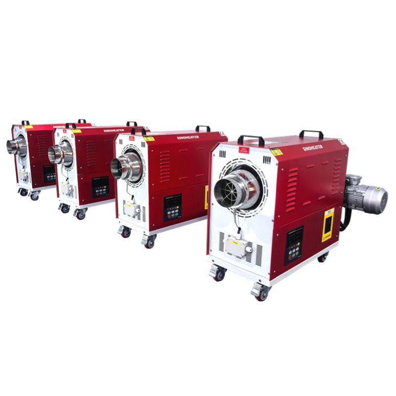
Hot Air Blower Electric Heating Air Circulation Working Principle
Core Components That Drive the Circulation System
A typical electric hot air circulation system relies on three interconnected parts to move and heat air consistently. The first part is the blower unit, which generates steady airflow to push ambient or recirculated air through the entire loop. The second is the electric heating assembly, where electrical energy converts directly into thermal energy to raise air temperature. The third is the integrated control and protection circuit, which adjusts operation parameters in real time to maintain stable performance.
Each part works in sync rather than operating independently. Even a small mismatch between blower speed and heating output can break the smooth flow of hot air, leading to uneven temperature distribution across the circulation path.
Airflow Generation and Initial Delivery
When the system receives power, the blower starts running first before any heating element activates. This step follows a standard safety rule to prevent heating components from overheating without passing air to carry away heat. The blower draws in surrounding air through a filtered inlet, then pushes it toward the heating section at a calibrated, consistent speed.
This initial airflow is not heated yet, but its steady speed lays the foundation for uniform heat exchange later. Many industrial systems set a 3 to 5 second delay between blower startup and heating activation to ensure full airflow coverage across all heating surfaces.
Electric Heat Conversion Process
Once the airflow is fully established, power is supplied to the electric heating elements. Most systems use coiled resistance wires or finned tubular heating elements that generate Joule heat immediately when current passes through them. The incoming cool air flows directly over and around these high-temperature elements, absorbing thermal energy through forced convection.
The finned or corrugated surface design on many heating elements expands the contact area between air and heat source, cutting down heat loss and boosting overall heat exchange efficiency. This direct contact ensures the air picks up heat quickly, rather than letting energy dissipate into the surrounding casing.
Closed-Loop Air Recirculation Mechanism
After the air is heated to the target temperature, it is not fully vented out of the system. Instead, a large portion of the used hot air is guided back into the inlet side of the blower, mixing with a small amount of fresh ambient air to form a continuous closed loop. This design reduces unnecessary energy waste by reusing residual heat that would otherwise be released into the open environment.
The recirculation ratio can be adjusted based on specific working scenarios. For processes that need extremely high temperatures, the recirculation proportion can go above 80% to keep heat loss at a very low level. For applications that require frequent air renewal, a smaller recirculation ratio is used to balance heat efficiency and air freshness.
Waste Heat Recovery and Reuse
As the circulated hot air completes its work in the target process, it still carries a large amount of residual heat that has not been fully used. The circulation system channels this slightly cooled air back through a dedicated recovery path, instead of letting it escape directly. The recovered air is fed back to the front of the heating assembly, where it mixes with newly incoming air and gets reheated to the set working temperature.
This step cuts down the total energy needed to heat fresh cold air from room temperature every cycle. In many continuous operation scenarios, waste heat recovery can reduce overall energy consumption by more than 40% compared to a single-pass, no-recirculation hot air setup.
Temperature Feedback and Dynamic Adjustment
High-precision temperature sensors, usually K-type thermocouples, are installed at key points along the airflow path, including the main hot air outlet and the recirculation air return inlet. These sensors send real-time temperature data back to the control unit, which compares the actual measured value with the pre-set target temperature.
If the outlet air temperature is lower than the set value, the control unit increases power supply to the heating elements to raise heat output. If the temperature exceeds the upper limit, it reduces or temporarily cuts off power to the heating assembly. This continuous, real-time feedback loop keeps the circulated hot air temperature stable within a narrow range, even when external ambient conditions change.
Safety Interlocks and Continuous Operation Logic
A well-designed electric hot air circulation system includes multiple layered protection mechanisms that prevent common faults such as no-load dry burning, airflow blockage, or motor overload. These protections do not interfere with normal operation, but they trigger immediate corrective actions the moment an abnormal condition is detected. All protection settings follow standard industrial safety guidelines for electric heating and airflow equipment.
Blower-Heater Interlock Protection
The most fundamental safety rule in the whole system is the strict sequence between blower and heater operation. The heating elements can never receive power before the blower reaches its full stable operating speed. Even if a user accidentally sends a heating activation signal, the interlock circuit will block power to the heating assembly until it detects sufficient airflow through the system.
When the system is shut down, the heating elements stop working first, and the blower keeps running for an extra period to carry away residual heat from the heating assembly. This prevents leftover high temperature from damaging internal components or causing material aging on the heating element surface.
Differential Pressure Monitoring for Airflow
Differential pressure sensors are installed between the air inlet and air outlet of the heating section. These sensors measure the pressure difference across the heating assembly, which directly reflects whether the airflow is flowing at the normal designed speed. If the airflow gets blocked by dust, debris, or a faulty blower, the pressure difference will drop below the safe threshold.
Once this abnormal reading is detected, the control unit cuts off power to the heating elements immediately, and sends out an alarm signal to notify operators. This protection adds an extra safety layer even if the initial blower-heater interlock encounters an unexpected fault.