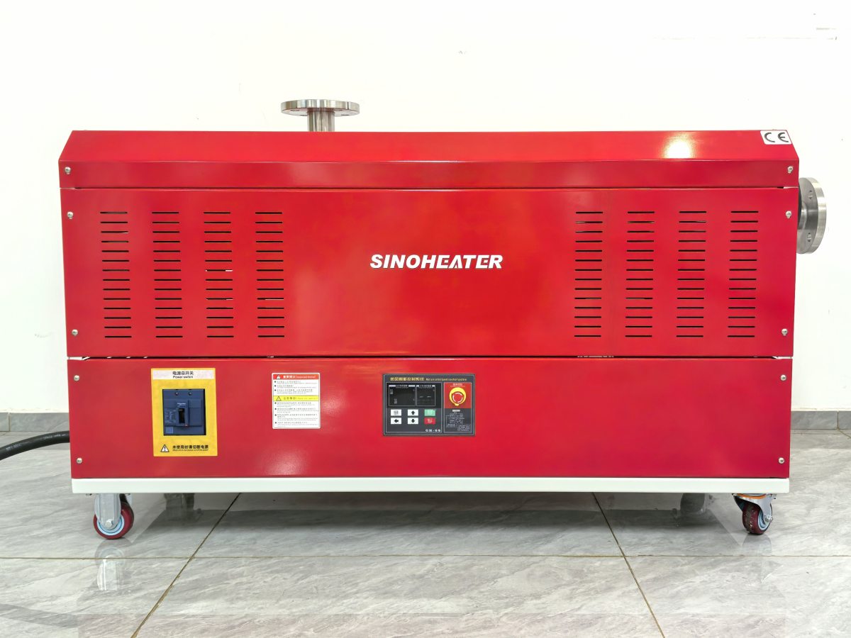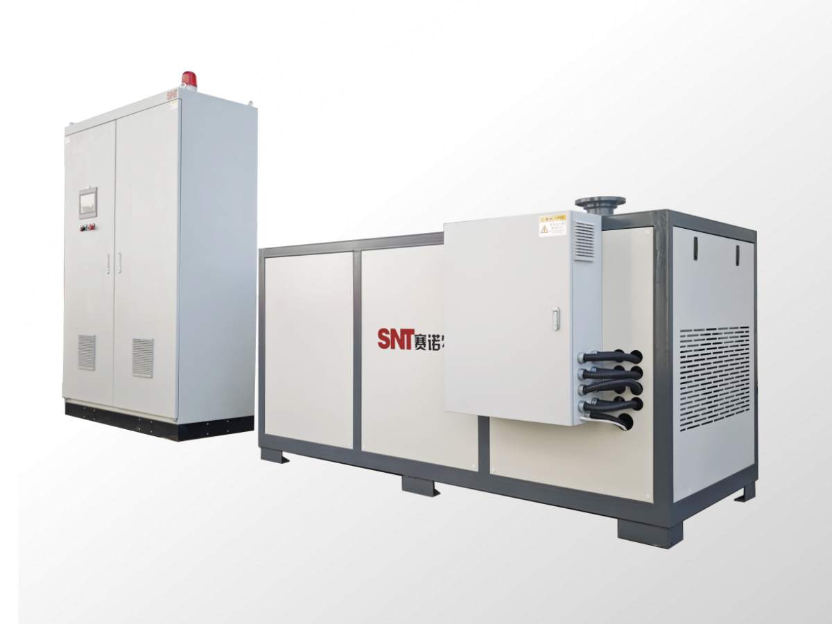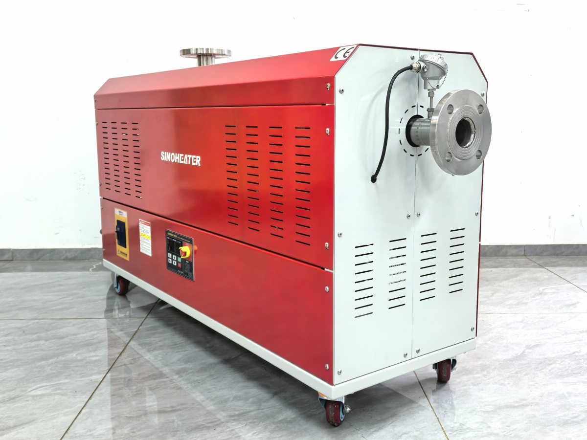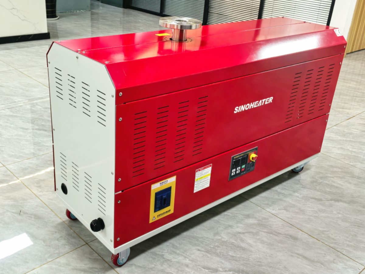
The service life of the heating tube directly determines the continuous operation stability of the hot air blower in long-cycle industrial applications. A set of standardized test indicators helps engineering teams verify the durability of core components before formal deployment, avoiding unexpected downtime caused by premature component failure. These test indicators are designed based on real operating conditions, covering electrical performance, thermal cycle resistance, structural stability and other key dimensions to ensure that the test results can truly reflect the actual service life under working load.
Rated Voltage Cycle Endurance Test
This test is carried out under full heat dissipation conditions, where the heating tube is energized at rated voltage for one hour and then powered off for half an hour to cool down to room temperature. This cycle repeats continuously until the component fails. The total accumulated operating time before failure is recorded as the basic reference index of service life. In the test process, the ambient air flow rate is kept consistent with the design parameters of the hot air blower, so that the heat generated by the heating tube can be taken away in time, avoiding additional thermal stress caused by local overheating.
Rapid Life Simulation Test Under Simulated Working Conditions
This test does not simply increase the power to speed up the failure process, but first restores the actual surface load, ambient temperature and matching clearance of the heating tube in the hot air blower. After these parameters are consistent with the on-site operating environment, the power is appropriately increased to shorten the test period. Each power-on and power-off cycle corresponds to the equivalent of one hour of actual operation, and the total number of cycles completed before the heating tube fails is converted into the estimated service life. This method can quickly screen out unqualified structures in a short time, and the test results are more consistent with the real operation data than the simple overload test.
Electrical Performance Retention After Long-Term Operation
After the heating tube completes the specified number of test cycles, multiple electrical performance indicators need to be re-tested to evaluate its performance retention rate. The resistance value of the heating element should remain within the allowable deviation range of the initial design value, and the insulation resistance between the heating element and the outer shell should not drop below the safety threshold. The leakage current under rated working voltage must be controlled within the standard range, and no breakdown or flashover phenomenon occurs during the dielectric strength test. These indicators ensure that even after thousands of hours of operation, the heating tube still maintains sufficient electrical safety.
Thermal Cycle Resistance and Structural Integrity Check
During the test, the heating tube goes through repeated rapid heating and cooling processes to simulate the temperature rise and fall cycle of the hot air blower during frequent start and stop. After the specified number of cycles, the surface of the heating tube is visually inspected for discoloration, cracking, warping or local oxidation. The sealing position at both ends of the heating tube should not have air leakage or aging and falling off, and the internal heating element should not have displacement or breakage due to thermal expansion and contraction. This set of indicators effectively verifies the long-term stability of the material and structure under alternating temperature loads.
Load Matching Verification Under Extreme Working Conditions
This test adjusts the surface load of the heating tube to the upper limit of the design range, and continuously operates under the maximum air temperature and minimum air flow that the hot air blower may encounter. The test duration is not less than one-tenth of the rated life index. After the test, the heating tube should not have local overheating melting, burnout or performance degradation beyond the allowable range. This indicator is used to confirm that the heating tube will not suffer sudden life attenuation when the system encounters transient working condition fluctuations, and maintains consistent durability under different load combinations.