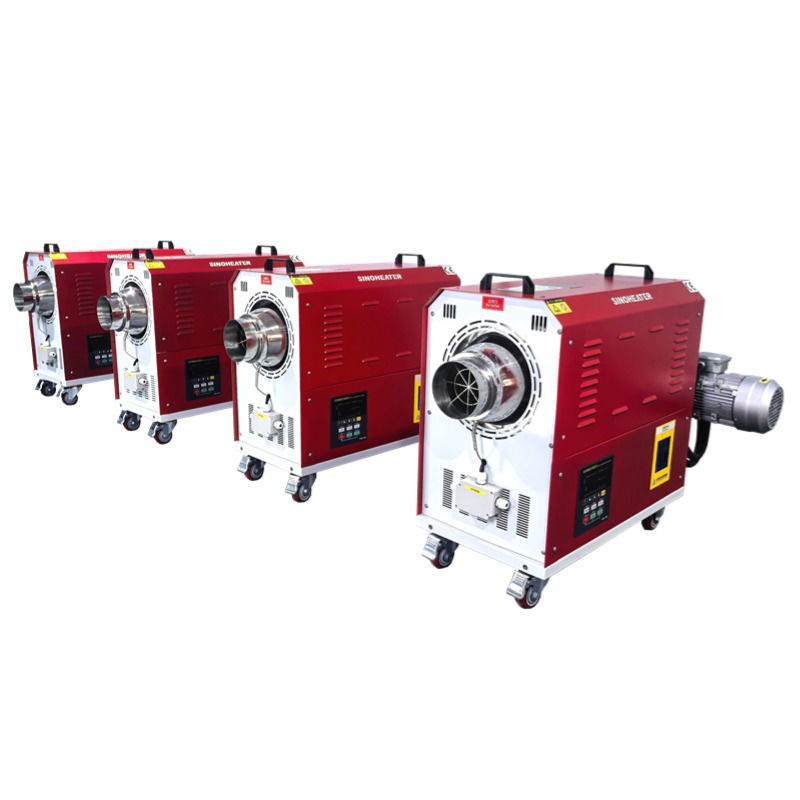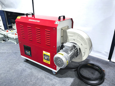
When sourcing a high-performance hot air blower with large air volume, understanding the core fan frame size parameters is critical to ensure seamless integration with existing ductwork, equipment enclosures, and operational workflows. These dimensions directly impact airflow efficiency, installation feasibility, and long-term stable performance, making them non-negotiable reference points for engineers, facility managers, and industrial procurement teams.
Outer Mounting Flange Dimensions
The outer mounting flange refers to the flat, extended perimeter of the fan frame that sits against the connection surface of ducts or equipment housings. Key measurements here include the overall length and width of the flange plate, the thickness of the metal or composite material used for the flange, and the exact distance between the center points of adjacent mounting bolt holes. These values determine whether the blower can be secured firmly without gaps that cause air leakage, which would reduce effective air volume by 15-25% even with minor misalignment. Users also need to confirm the flange’s edge profile, as some custom installation spaces require a rounded or beveled flange edge to avoid interference with surrounding structural components.
Inner Air Outlet Diameter
The inner air outlet diameter is the clear, unobstructed opening on the fan frame where high-volume hot air is discharged into the connected system. This parameter must match the inner diameter of the connected duct or inlet port of downstream equipment to prevent sudden airflow constriction or expansion that generates unnecessary turbulence. Even a 10mm mismatch between the fan frame’s inner outlet diameter and the duct inner diameter can create enough backpressure to cut the rated large air volume output significantly. For rectangular outlet frames, the paired length and width of the inner opening are measured instead of a single diameter value, with the aspect ratio of these two dimensions directly influencing the uniformity of airflow distribution across the outlet face.
Frame Overall Depth and Internal Clearance
The overall depth of the fan frame covers the full distance from the rear mounting surface that holds the motor assembly to the front face of the air outlet flange. This measurement must fit within the reserved installation cavity in equipment or on facility mounting brackets, as insufficient depth space can force users to modify surrounding structures or compromise the safety gap around the operating motor. Internal clearance inside the frame refers to the gap between the inner wall of the frame and the outer edge of the rotating fan impeller. A properly calibrated clearance keeps airflow loss to a minimum while eliminating the risk of contact between moving and stationary parts even under long hours of high-speed operation at elevated working temperatures. This set of parameters also accounts for the space reserved for heat dissipation around the impeller chamber, preventing overheating that would degrade consistent large air volume delivery over extended runtime.