
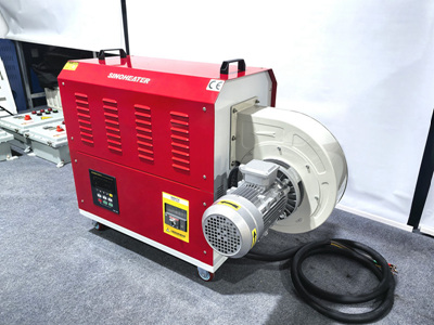
When developing a sealed air chamber anti-leakage structure for hot air blowers, the core priority is to maintain consistent internal air pressure, prevent uncontrolled hot air escape, and ensure stable airflow output even after thousands of hours of continuous operation. This structure must work in harmony with the blower’s heating elements and airflow path, avoiding common failure points like seal aging, thermal deformation, and stress cracking that often appear in basic air chamber designs.
Multi-Layer Joint Sealing for High-Temperature Contact Surfaces
Every connection point between the air chamber’s separate components is a potential leakage risk, especially when exposed to constant cycles of rapid heating and cooling. A single sealing layer rarely holds up over long-term use, which is why a layered sealing strategy is essential for reliable performance.
- Apply a continuous, thin layer of high-temperature resistant adhesive along the full perimeter of the joint, making sure there are no small gaps, air bubbles, or surface contamination left on the contact surfaces before the two parts are pressed together.
- Add a secondary soft sealing strip that sits in a precision-machined groove along the joint edge, so that even if the adhesive experiences minor thermal expansion mismatch, the strip can fill in any tiny gaps that form under pressure.
- Lay a thin layer of high-temperature resistant foil tape over the outer seam of the joint, creating a final physical barrier that blocks any remaining micro-leaks and prevents dust from working its way into the sealing layers over time.
Optimized Flange Connection System for Airtight Stability
Flange connections are the most common assembly method for hot air blower air chambers, but poorly designed flanges are a frequent source of hidden leakage that is hard to detect during routine inspections. The right flange structure distributes pressure evenly across the entire sealing surface, avoiding uneven compression that creates weak leakage points.
- Use an insert-type flange design with a built-in positioning ridge that aligns the two connecting parts perfectly, so the sealing gasket stays centered and does not shift out of place when the flange bolts are tightened.
- Select a flange structure with a fully enclosed gasket groove that holds the sealing material in place, preventing it from being squeezed out under high internal air pressure or softened by long-term exposure to circulating hot air.
- For hot air blowers that operate at higher internal pressures, use a hidden flange layout that places all sealing surfaces inside the air chamber’s outer wall, reducing exposure to external temperature changes that can cause uneven material deformation.
Reinforced Sealing for Corners and Special Flow Path Areas
Corners, tees, and elbow sections inside the air chamber experience uneven airflow stress and temperature gradients, which makes these spots far more likely to develop leaks over time than flat, straight sealing surfaces. These areas need targeted reinforcement that accounts for their unique mechanical and thermal loads.
- Use prefabricated one-piece corner sealing components instead of cutting and joining flat sealing materials on site, which eliminates the small, hard-to-seal gaps that form at manually assembled corner joints.
- Add an extra 2mm thick sealing layer at all tee and elbow connection points, to compensate for the higher stress concentration that occurs when hot air changes direction and creates localized pressure spikes.
- Design a small pressure relief buffer zone around these special areas, so that sudden airflow fluctuations do not apply direct, repeated impact force to the sealing edges, slowing down long-term material fatigue and cracking.

