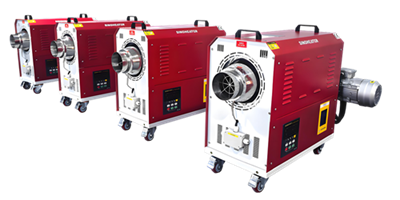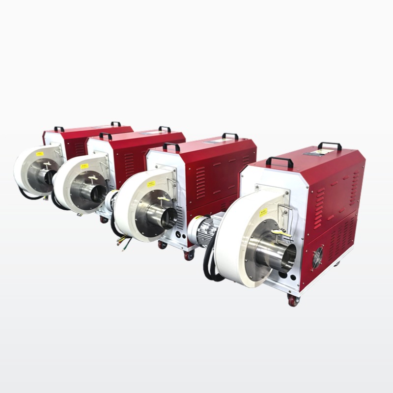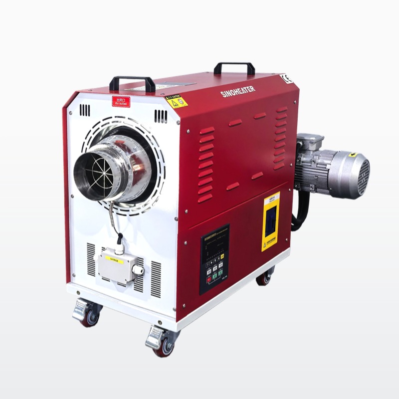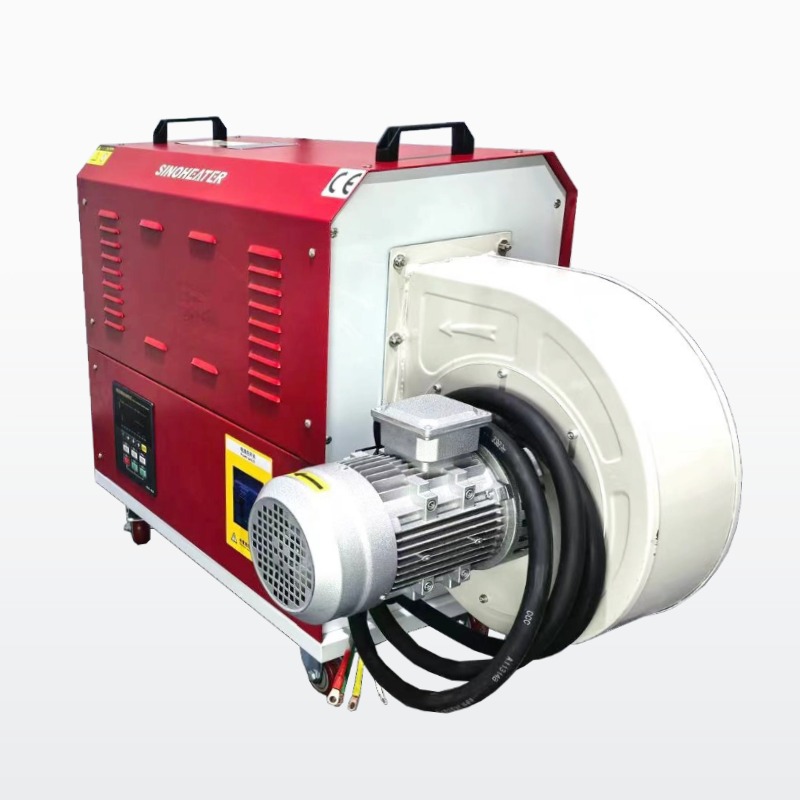
The internal structure of a hot air blower air circulation channel is a carefully engineered system designed to guide airflow efficiently, minimize energy loss and maintain stable thermal performance over long operating hours. Every internal contour and connection point is optimized based on fluid dynamics principles, avoiding unnecessary turbulence, local pressure drops or uneven heat distribution that often occur in poorly designed systems.
Air Inlet and Primary Flow Acceleration Zone
The air inlet section is designed with a gradually converging cross-sectional area, which increases the speed of incoming air smoothly before it enters the main heating zone. This design avoids sudden air speed changes that may cause energy loss or generate loud noise during operation. The inner wall of this section uses a polished surface finish to reduce airflow friction resistance, allowing the air to maintain a stable laminar flow state as much as possible. No sharp corners or abrupt changes in direction are placed here, which prevents the formation of local vortexes that may block normal air passage or cause pressure fluctuations.
Heating Core Surrounding Flow Distribution Structure
The area surrounding the heating core features a specially designed guide structure that distributes the incoming air evenly across the entire heating surface. Multiple small, curved guide plates are arranged around the heating elements, gently directing the airflow to cover every part of the heating area without leaving any unheated blind spots. This layout ensures the maximum amount of cold air makes direct contact with the high-temperature heating surface, greatly improving overall heat exchange efficiency. The guide plates are fixed with high-temperature resistant brackets that do not vibrate or deform under the impact of high-speed airflow, maintaining stable flow distribution performance even after thousands of hours of continuous operation.
Outlet Channel Smooth Transition and Pressure Recovery Design
After passing through the heating zone, the hot air enters an outlet channel with a gradually expanding cross-section, which slows down the airflow speed and converts part of the dynamic pressure back into static pressure. This pressure recovery process reduces the energy consumption of the internal fan and improves the overall system efficiency. The inner wall of the outlet channel uses a special multi-curve transition design, which guides the airflow to change direction smoothly without creating separation or backflow. The entire outlet section is kept as straight as possible to minimize additional resistance, ensuring the hot air can flow out steadily with stable temperature and pressure parameters, ready for various downstream application needs.